Operating Conditions
The purpose of this guidelines is to ensure the continuing operational integrity of generators.

Operating conditions (startup and shutdown) that have forced units off-line or have damaged or shortened the life of turbine (or generator) components in the past are highlighted in the guideline to prevent recurrences in the future.
Startup Operation
In addition to monitoring the various generator support systems for cooling and lubrication, electrical parameters, temperatures, and vibration, inattention to the following areas has caused problems in the past:
Problem #1
At no time should excitation interlocks or protective relay functions be bypassed or disabled for the purpose of energizing a generator’s direct current (DC) field winding.
Problem #2
For generators requiring field pre-warming, the manufacturer instructions and established procedures should be followed relative to the allowable field currents.
Problem #3
A generator field should not be applied or maintained at turbine speeds above or below that recommended by the manufacturer. On cross-compound units where a field is applied at low speeds or while on turning gear, extreme caution must be exercised.
Should either or both shafts come to a stop, the field current should immediately be removed to prevent overheating damage to the collector or slip rings.
Problem #4
After the field breaker is closed, the generator field indications should be closely monitored. If a rapid abnormal increase occurs in field current, terminal voltage, or both, immediately open the field breaker and inspect the related equipment for proper working condition before reestablishing a field.
Problem #5
During off-line conditions, at no time should the field current be greater than 105% of that normally required to obtain rated terminal voltage at rated speed in an unloaded condition.
Typically, turbo-generators are designed to withstand a full load field with no load on the machine for only 12 seconds; after that, severe damage can occur to the stator core iron laminations.
Problem #6
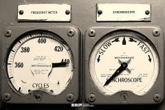
When synchronizing a generator to the system, the synchroscope should be rotating less than one revolution every 20 seconds Phase angle differences should be minimized and no more than 5 degrees out of phase when the circuit breaker contacts close.
Phase angle differences as little as 12 degrees can develop shaft torques as high as 150% of full load and damage shaft couplings and other turbine and generator components. Manufacturers usually recommend limiting maximum phase angle differences to 10 degrees.
It is also desirable that incoming and running voltages are matched as closely as possible to minimize reactive power flow to or from the electrical system.
In general, the voltages should be matched within 2% at the time of synchronization. The speed of the turbine should be slightly greater than synchronous speed prior to breaker closure to help ensure that the unit will not be in a motoring condition following connection to the electrical system, and the generator voltage should be slightly higher to ensure var flow into the system instead of into the generator.
Shutdown Operation
Normally, units are removed from service through operator initiation of distributed control system (DCS) commands or turbine trip buttons that shut down the prime mover.
Closure of steam or fuel valves will then initiate anti-motoring or reverse power control circuits that isolate the unit electrically by opening the generator circuit breakers, field breakers, and, depending on the design, unit auxiliary transformer (UAT) low side breakers. If limit switch circuitry or anti-motoring/reverse power relays fail to operate properly, the unit may stay electrically connected to the system in a motoring condition.
On steam units, the low pressure turbine blades are impacted the most, with typical withstands of 10 minutes before damage.
However, the unit can be safely removed from service with the following operating steps:
Operating step #1
Verify that there is no steam flow or fuel flow in the case of combustion turbine units to ensure that the unit will not overspeed when the generator circuit breaker(s) are opened.
Operating step #2
Transfer the unit auxiliary power to the alternate source if opening the unit breakers will de-energize the UAT.
Operating step #3
Reduce or adjust the generator’s output voltage (voltage regulator) until the field current is at the no load value, and transfer from automatic voltage regulator mode to the manual mode of operation.
Operating step #4
Open the generator circuit breaker(s).
Operating step #5
Open the generator field breaker.
Reference // Electrical Calculations and Guidelines for Generating Stations and Industrial Plants – Thomas E. Baker (Purchase from Amazon)





This program is great it has helped me run the plant so well .
i like the site
Today most of the power stations are using Auto-synchronizers and the job is no more done manually. The limits indicated for phase angle (namely 10 degrees) is too liberal for the rating of generators being installed in modern power plants.
Please include some case studies on systems engineering/designs of running power plants , grids and substations.