
Cybersecurity of substations
Multiple layers are necessary to ensure the cybersecurity of substations. Cryptography allows authentication of devices, but not all attacks can be prevented with these measures. Firewalls and “air gaps” can be circumvented through existing remote access tunnels, or through maintenance computers directly attached to IEDs or the station bus.
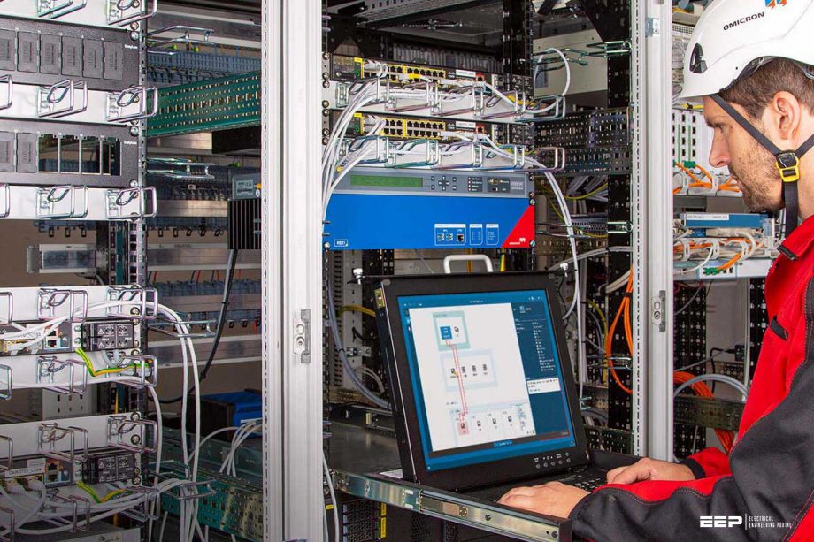 Improving the cybersecurity of substations using intrusion detection (photo credit: OMICRON)
Therefore, measures are needed to detect threats in the substation to enable quick response and to minimize consequences.
This technical article will describe the security requirements of substations and a new approach for detecting threats in these networks. Subsequently, an approach specifically developed for the IEC 61850 station and process bus will be described.
- Attack vectors of a substation
- Security and IEC 61850
- Encryption
- Defense in depth
- Requirements for IDS in Substations
- Learning-based systems
- The approach
- Functional security monitoring
- Developed with PAC engineers
- Alert Display
- Asset Inventory
- Configuration
- What happens in case of an alarm?
- Cybersecurity of the IDS itself
- Summary
Attack vectors of a substation
Let us define a cyber attack on a substation as an event where an adversary modifies, degrades, or disables a service of at least one protection, automation, or control device within the substation.
Looking at Figure 1, a typical substation can be attacked through all paths marked in red. The most frequent attack vector used is the connection from corporate IT (1), which was exploited in Ukraine 2016 attack on a substation. This connection can be permanent, for connecting to servers in the corporate IT, or temporary for remote maintenance.
An attacker could also enter through the control center connection (2) – regardless of which SCADA protocol is used. Another entry point is through engineering PCs (3) connected to substation equipment or the network.
When a protection engineer connects their PC to a relay to change parameters, malware on the PC could, in turn, install malware on the relay in a comparable way to what happened with PLCs in the Stuxnet cyber attack in 2010.
Laptops used for testing the IEC 61850 system are often directly connected to the station bus which is also a potential way to infect IEDs (4). For this reason, new IEC 61850 testing tools are available which provide a cyber-secure separation between the Test PC and the substation network.
This leaves the testing device itself (5) as a potential attack vector.
Because of this, it is important that test set vendors invest in hardening their devices to make sure that this vector is not feasible for an attacker to exploit.
The storage location of settings (3a) and test documents (4a) also represents an attack vector. This storage server thus also belongs to the critical perimeter. Therefore, it also makes sense to introduce a separate, isolated and protected data management solution for such data.
Security and IEC 61850
A frequent question about cybersecurity in IEC 61850 substations is: “What happens if an attacker injects a trip GOOSE into the station bus – how can I prevent that?”
For this, we should not focus on the attacker having physical access to the substation network. This situation is also possible through other measures: an infected engineering or testing PC connected to the station bus, or even that an infected IED could start injecting GOOSE.
In this context, the status and sequence numbers in the GOOSE message are quite often presented as GOOSE “security mechanisms”.
However, such measures should merely be called “safety mechanisms”, because any adversary can listen to the current status and sequence number and inject suitable values. Also the source MAC address of the GOOSE packet can be spoofed easily by the attacker. The IED receiving the GOOSE has no other option than to react on the first GOOSE received with correct source MAC and correct status/sequence number.
The same of course applies to the sample counter in sampled values.
Note that it is not necessary to encrypt the message to get these features. To deliver and maintain these authentication keys for each IED, a key management infrastructure is needed inside the substation.
Because of this, these GOOSE security mechanisms have not gained widespread use, yet – but they will. The same applies to MMS and role-based access control.
Encryption
Encryption has not been mentioned, though it is often seen as the silver bullet for security. The IEC 62351 standard also provides encryption for GOOSE and MMS. However, in the substation environment there are only a few applications imaginable where confidentiality of messages is important.
If messages cannot be tampered with (integrity) and the originator can be verified (authentication) – which is fulfilled by using authentication in GOOSE and MMS, it is not necessary to encrypt the messages. One example where encryption could be necessary is if routable GOOSE (R-GOOSE) are transmitted over an unencrypted communication path.
Encryption also makes a later analysis of traffic recordings difficult and it impedes monitoring approaches such as the ones described below.
Defense in depth
Intrusion Detection System (IDS)
Most IEC 61850 substations built up until now have not implemented IEC 62351. Even in substations where GOOSE and MMS with authentication codes are applied, infected devices in the network could still infect other devices or affect availability by disturbing the communication system.
Therefore, most security frameworks recommend the usage of “Intrusion Detection Systems” (IDS), a well-known term from classic IT systems, to detect malicious activity on the network to be able to respond quickly and minimize the damage..
Such IDS, like OMICRON’s StationGuard, are now becoming more common in the power system domain.
Requirements for IDS in Substations
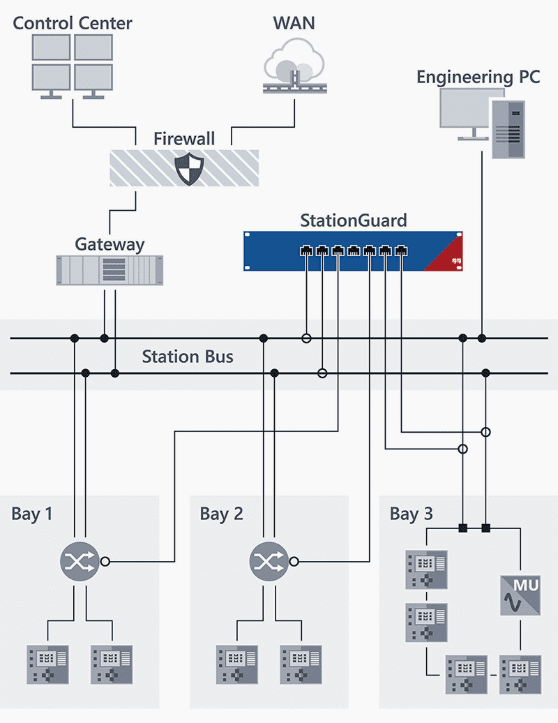
In an IEC 61850 substation, an IDS would be connected as depicted in the Figure 2. Mirror ports, , also known as SPAN ports on all relevant switches forward a copy of all network traffic to the IDS. The IDS inspects all network traffic communicated over these switches.
To be able to analyze the most important traffic between the gateway and the IEDs, the IDS should, as a minimum, be connected to the switch next to the gateway and all other critical entry points into the network.
The bay-level switches don’t usually need to be covered as typically only multicast traffic (GOOSE, Sampled Values) originates from there.
To ensure that all unicast traffic in all network branches is analyzed, it is essential that all switches are mirrored into the IDS, which is not always possible if switch chips integrated into the IEDs are used at the bay level.
However, IDS from classic IT are not suitable for the substation environment. While classic IT security is concerned with high-performance servers with millions of connections at the same time, substation IT security deals with devices with limited resources, custom operating systems, real-time demands, and specialized redundancy protocols.
Thus, a substation IDS must be able to detect attacks without any previous knowledge about what the attack might look like, and that is exactly what OMICRON’s StationGuard does. This is a very different approach than that of a virus scanner, which has a list of virus signatures it looks for.
Learning-based systems
To be able to detect unknown attacks, many vendors use a “learning-phase” approach, also known as “baseline-approach“. Such systems look at frequency and timing of certain protocol markers to attempt to learn the usual behavior of the system.
After the learning phase is complete, an alarm will be raised if one of the markers is significantly outside the expected range. This has the effect that false alarms are triggered for everything that did not occur during the learning phase, such as protection events, switching or automation actions, or routine maintenance and testing. Because these systems don’t understand the semantics of the protocols, the alarm messages are expressed in terms of technical protocol details.
Hence, alarms can only be examined by an engineer skilled in the protocol details and familiar with IT network security. The engineer examining the alarm must also know about the operational situation to judge if certain IEC 61850 protocol events correspond to valid behavior.
Therefore, a high number of false alarms occur for every substation, all of which require examination by highly skilled personnel.
This often leads to alarms being ignored or alarms being discarded without investigation, and ultimately the IDS being switched off.
The approach
For IEC 61850 substations, the whole automation system, including all devices, their data models, and their communication patterns is described in a standardized format – the SCL (System Configuration Language). System Configuration Description (SCD) files normally also contain information about primary assets and, for an ever-increasing number of substations, even the single-line diagram is present.
This information allows a different approach to be used for detecting intrusions:
This process is possible without the need for a learning phase, just by configuration from SCL. This approach is implemented in OMICRON’s new functional security monitoring system StationGuard.
Functional security monitoring
In essence, very detailed functional monitoring is produced to detect cyber threats in the network. Because of the detail level of the verification, it is not only cybersecurity threats like malformed packets and disallowed control actions that are detected, but also communication failures, time synchronization problems, and consequently also (certain) equipment failures.
If the single-line diagram is known to the system, and measurement values can be observed in MMS (or even through Sampled Values) communication, the possibilities of what can be verified are endless.
Example
For example, for GOOSE alone there are 35 alarm codes available for things that could go wrong. These range from simple stNum/sqNum glitches (as explained above) to more complex issues, such as too long transmission times. The latter is detected by accurately measuring the difference between the EntryTime timestamp in the message and the arrival time at StationGuard.
If this network transmission time is significantly longer than 3 ms for a “protection” GOOSE (referring to IEC 61850-5), it indicates a problem in the network or in the time synchronization.
What is done for MMS communication?
From the system model (from the SCL) it is known which Logical Nodes control which primary assets. Thus, it can be distinguished between correct / incorrect, and critical / noncritical actions. Switching a circuit breaker and switching the IEC 61850 test mode use the same sequence in the MMS protocol (select-before-operate), but the effect in the substation is quite different.
So, if the Test PC from Figure 5 switches the test mode on a relay this may be a legitimate action during maintenance, but it is most probably not legitimate that the Test PC operates a breaker.
There will be a more in-depth look at this example in the following paragraphs.
Developed with PAC engineers
Research on this approach started in 2011. Spinoffs of this concept, the 24/7 functional supervision of SV, GOOSE and PTP time synchronization, have been available in a distributed and hybrid analysis device (OMICRON DANEO 400) since 2015. Moreover, feedback from many other utilities worldwide, as well as some proof-of-concept installations, found its way into our development.
In 2018, one of the first proof-of-concept installations was installed in a 110kV substation of the Swiss generation and distribution utility CKW and has been running since then.
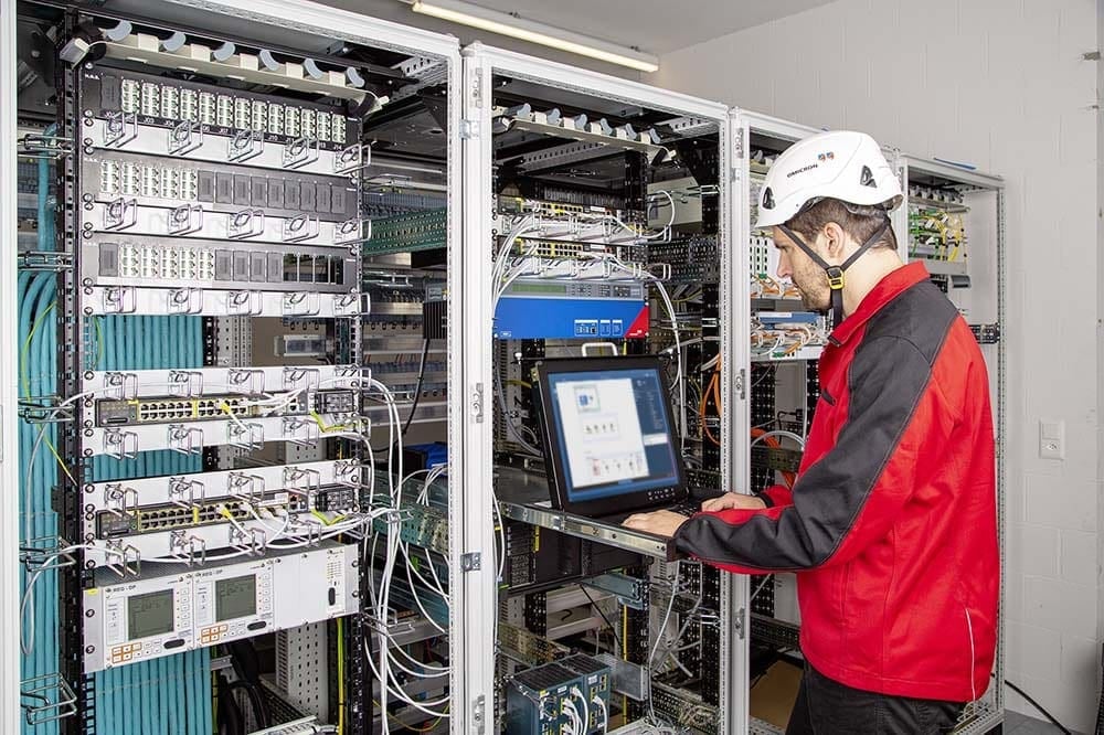
Figure 4 shows the installation in a new greenfield substation in 2019. In this setup, all traffic from the “core” switch was mirrored to StationGuard. This ensures that all the communication from the gateway to and from all IEDs is visible.
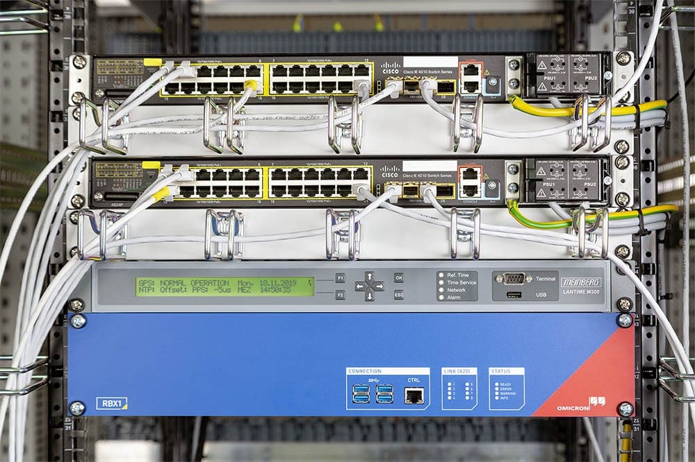
Because remote maintenance connections also enter through that switch, all this traffic can also be inspected by StationGuard. Since GOOSE communication is multicast, and because the network setup allows it, all GOOSE from the IEDs in the substation bays are also visible to StationGuard.
Alert Display
Besides the avoidance of false alarms, it is also of vital importance that the alert messages delivered are understandable to the engineers who are responsible for the operation of the protection, automation and network functions within the substation.
Figure 5 shows a screenshot of the graphical alarm display: The alarm is shown as an arrow from the active participant (Laptop 1) performing the prohibited action, and the “victim” of the action – a bay controller in bay Q01.
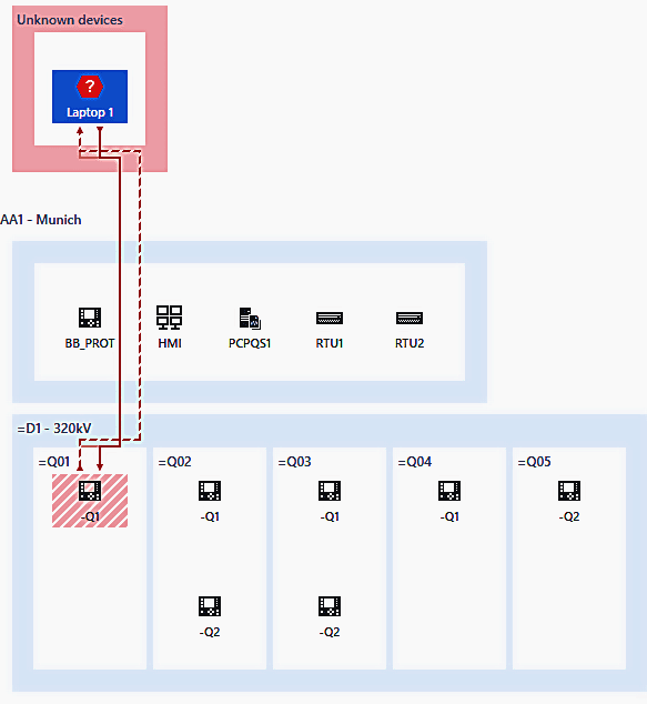
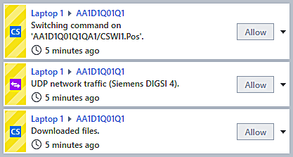
Figure 6 reveals details about that alarm – a circuit breaker was operated (using an MMS control sequence), which is not allowed for an unknown PC. Further, this laptop also created connections using a vendor protocol and downloaded files over MMS.
The alert details would reveal additional information, such as the name of the downloaded file.
Asset Inventory
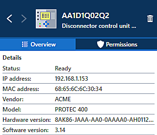
All devices communicating in the network are detected and displayed. For each device detected, information from captured network traffic is aggregated with information from SCL (System Configuration Language). This allows to show vendor, model, and firmware version where available.
Figure 7 shows the aggregated information for a cyber asset including device description and name from the project SCD file. All detected assets and their information can also be exported.
Configuration
As previously mentioned, no learning phase is required. The detection starts right from the time that the device is powered up and it cannot be turned off – for security reasons. Until the SCD file of the substation is loaded, all IEDs will be detected and presented as unknown devices. Once the SCD file is loaded, the IEDs will be indicated as known devices and the substation structure is assembled into a “zero-line” diagram, as it was introduced with StationScout.
The configuration can also be prepared in the office and then installed on site, one after the other, with fast commissioning. If not all IEDs were engineered into one file (these things happen), then additional IEDs can also be imported one by one.
Once the import is done, the user can add roles such as “Test PC”, “Engineering PC”, etc. to any remaining unknown devices.
What happens in case of an alarm?
It is important to note that the StationGuard is purely passive, if an action is “not allowed” it will trigger an alarm. This alarm can be communicated to the Gateway/RTU and control center or to a separate system collecting security alerts – known as a Security Information and Event Management (SIEM) system using the Syslog protocol.
Depending on the chosen hardware variant, user-definable binary outputs are available to be wired directly to the RTU. In this case, the alarm signalization happens without network communication and the alarms can be integrated into the normal SCADA signal list like any other hard-wired signal from the station.
Cybersecurity of the IDS itself
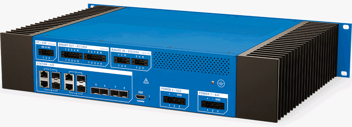
As we know from b-grade movies, burglars always attack the burglar alarm system first. So what about the security of this alarm system? An important aspect is that a standalone, secure hardware is used and not a virtual machine. Both hardware variants of StationGuard, the mobile (MBX1) and the 19” rack-variant for permanent installation (RBX1), have the same platform hardening.
They both have a secure cryptoprocessor chip according to ISO/IEC 11889. This ensures that cryptographic keys are not stored on the flash storage but in a separate chip which is protected against tampering.
By installing the OMICRON certificates on this chip during production, a secure, measured boot chain is created. This means that each step in the firmware bootup process verifies the signatures of the next module or driver to load.
This makes sure that only software signed by OMICRON can be executed.
Many other mechanisms make sure that the processes on the device cannot be attacked or misused, so that the “defense in depth” approach is also applied deep into the software running on the device.
Summary
Substations provide multiple potential attack vectors for cyber attacks. If an attacker is able to influence one or more substations, this can have severe consequences for the grid. Therefore, effective cybersecurity measures must be implemented, not only in the control centers, but also in substations.
At the substation level, an approach for intrusion detection is available which provides a small number of false alarms and still low configuration overheads due to the power of the SCL. StationGuard not only detects security threats, but also functional problems in the configuration and communication is detected – which is also helpful in the FAT and SAT phase.
StationGuard displays detected events in the language of protection, automation and control engineers and thus offers the advantage that PAC and security engineers can work together to find the cause of events.
More information available at: www.omicronenergy.com/stationguard


Thank you for sharing the valuable content.
The electrical test and measurement range of products from Josts’ Electrical Division ensures performance and reliability in power generation, transmission and distribution equipments. Josts has rich experience of over eight decades in providing advanced technology products and systems dedicated to various applications in Electrical Industry. Josts has pioneered many concepts in electrical testing and measurement for various applications in India such as Insulation Testing,
It’s very nice information
This will greatly help in my daily activities and remind me to improves my skills as Electrical Engineer.
Good Morning for everybody
Please can I have the document in pdf format here my adresse [email protected].
Thanks a lot.