
Estimated Study Time: 9 minutes
Inductor, what is it?
We have all heard the term Inductor many times, but what is it? Well, it is a passive element designed to store energy in its magnetic field. Inductors find numerous applications in electronic and power systems. They are used in power supplies, transformers, radios, TVs, radars, and electric motors.
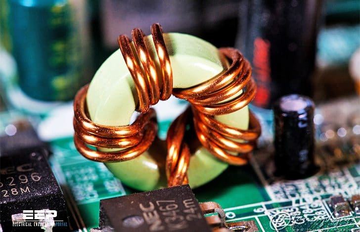 What is an inductor and how it works - facts you must NEVER forget (photo credit: Tamara Kwan via Flickr)
But in order to enhance the inductive effect, a practical inductor is usually formed into a cylindrical coil with many turns of conducting wire, as shown in Figure 1.
An inductor consists of a coil of conducting wire.

If current is allowed to pass through an inductor, it is found that the voltage across the inductor is directly proportional to the time rate of change of the current. Using the passive sign convention in following Equation (1):

where L is the constant of proportionality called the inductance of the inductor. The unit of inductance is the henry (H), named in honor of the American inventor Joseph Henry (1797–1878). It is clear from above equation that 1 henry equals 1 volt-second per ampere.
In view of equation above, for an inductor to have voltage across its terminals, its current must vary with time. Hence, v=0 for constant current through the inductor.
The inductance of an inductor depends on its physical dimension and construction. Formulas for calculating the inductance of inductors of different shapes are derived from electromagnetic theory and can be found in standard electrical engineering handbooks.
For example, for the inductor, (solenoid) shown in Figure 1,

where:
- N is the number of turns,
- l is the length,
- A is the cross-sectional area, and
- m is the permeability of the core.
We can see from equation above that inductance can be increased by increasing the number of turns of coil, using material with higher permeability as the core, increasing the cross-sectional area, or reducing the length of the coil.

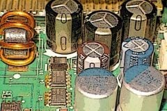
Like capacitors, commercially available inductors come in different values and types. Typical practical inductors have inductance values ranging from a few microhenrys (mH), as in communication systems, to tens of henrys (H) as in power systems. Inductors may be fixed or variable. The core may be made of iron, steel, plastic, or air.
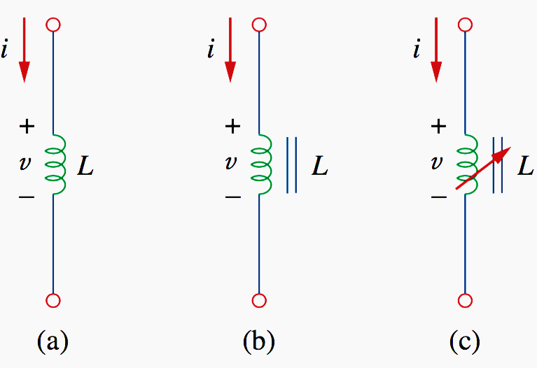
Common inductors are shown in Figure 2 above. The circuit symbols for inductors are shown in Figure 3, following the passive sign convention.
Equation (1) is the voltage-current relationship for an inductor. Figure 4 shows this relationship graphically for an inductor whose inductance is independent of current. Such an inductor is known as a linear inductor.
We will assume linear inductors in this technical article.

The current-voltage relationship is obtained from Equation (1) as:

Integrating gives:

or

where i(t0) is the total current for −∞ < t < to and i(−∞) = 0. The idea of making i(−∞) is practical and reasonable, because there must be a time in the past when there was no current in the inductor.
The inductor is designed to store energy in its magnetic field. The energy stored can be obtained from Equation (1). The power delivered to the inductor is:

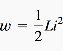
The energy stored is:

Since i(−∞) = 0,
Notes //
We should note the following important properties of an inductor:
NOTE 1 //
Note from Equation 1 that the voltage across an inductor is zero when the current is constant.
NOTE 2 //
An important property of the inductor is its opposition to the change in current flowing through it. The current through an inductor cannot change instantaneously.
For example, the current through an inductor may take the form shown in Figure 5(a), whereas the inductor current cannot take the form shown in Figure 5(b) in real-life situations due to the discontinuities. However, the voltage across an inductor can change abruptly.

NOTE 3 //
Like the ideal capacitor, the ideal inductor does not dissipate energy. The energy stored in it can be retrieved at a later time. The inductor takes power from the circuit when storing energy and delivers power to the circuit when returning previously stored energy.
NOTE 4 //
A practical, nonideal inductor has a significant resistive component, as shown in Figure 6. This is due to the fact that the inductor is made of a conducting material such as copper, which has some resistance.

This resistance is called the winding resistance Rw, and it appears in series with the inductance of the inductor. The presence of Rw makes it both an energy storage device and an energy dissipation device. Since Rw is usually very small, it is ignored in most cases. The nonideal inductor also has a winding capacitance Cw due to the capacitive coupling between the conducting coils.
Cw is very small and can be ignored in most cases, except at high frequencies. We assumeed only ideal inductors in this article.
Who was Joseph Henry?
Joseph Henry (1797–1878), an American physicist, discovered inductance and constructed an electric motor. Born in Albany, New York, Henry graduated from Albany Academy and taught philosophy at Princeton University from 1832 to 1846.
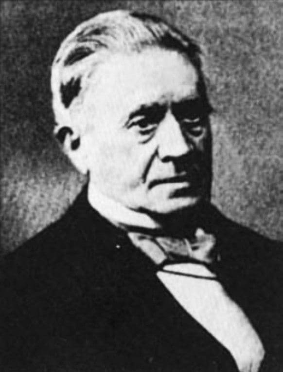
He was the first secretary of the Smithsonian Institution. He conducted several experiments on electromagnetism and developed powerful electromagnets that could lift objects weighing thousands of pounds. Interestingly, Joseph Henry discovered electromagnetic induction before Faraday but failed to publish his findings.
The unit of inductance, the henry, was named after him.
Reference // Fundamentals of electric circuits by Charles K. Alexander and Matthew N.O. Sadiku (Purchase hardcopy from Amazon)
Related electrical guides & articles


Edvard Csanyi
Hi, I'm an electrical engineer, programmer and founder of EEP - Electrical Engineering Portal. I worked twelve years at Schneider Electric in the position of technical support for low- and medium-voltage projects and the design of busbar trunking systems.I'm highly specialized in the design of LV/MV switchgear and low-voltage, high-power busbar trunking (<6300A) in substations, commercial buildings and industry facilities. I'm also a professional in AutoCAD programming.
Profile: Edvard Csanyi

Boring, a lot of theory. I mean it’s an article not a chapter of a textbook. BTW I am Electrical engineer.
I want the PDF of ” what is an inductor and how it works?”