
Estimated Study Time: 8 minutes
Allowable Electric Field
Bus height is also governed and calculated by the fact that allowable electric field due to live conductor at man height should be less than permissible value as per guidelines laid down by EPRI AC transmission Line Reference Book – 200kV and Above Third Edition.
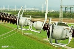
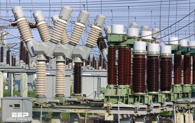 Influence Of Electric Field and Clearances In EHV AIS Substation (photo credit: libe.us)
This article is continued from: Clearance Requirements In EHV AIS Substation You MUST Respect
Conductor levels and different voltages
| Voltage level | First level | Second level | Third level |
| 765 kV | 14 m | 27 m | 39 m |
| 400 kV | 8 m | 15 m | 22 m |
| 220 kV | 5.9 m | 11.7 m | 16.2 m |
| 132 kV | 4.6 m | 7.5/8 m | 10.8/12 m |
Electric field and magnetic field and height of different conductor levels are interrelated.
The regular influence of electric field may be harmful to 400 kV – 765 kV switchyard staff health. There is no well defined guideline in India for the limits of electrostatic levels in substation.
Researches carried out in USSR had derived following limits of electric field intensity tolerable by human beings within a period of time.
| Field Intensity (KV/M) | Permissible duration (Minute per day) |
| 5 | Unlimited |
| 5-10 | 180 |
| 10-15 | 90 |
| 15-20 | 10 |
| 20-25 | 5 |
International Non-ionizing Radiation committee of the International Radiation Protection Association has suggested that continuous occupational exposure the working day should be limited to 10KV/mtr. Therefore, for safe working near charged equipment the electric field should not be more than 10KV/mtr at 1.8 meter level.
As per calculations and measurements carried out in 400 kV substations with 8 meter ground clearance and with 6 meter phase to phase distance, electric fields at various locations have been found to be well within the limit of 10KV/mtr.
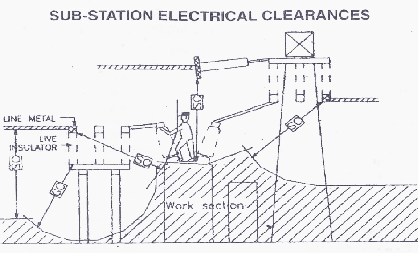
Sectional Clearance Or Safety Working Clearance
Section clearance is the distance between two sections of substation, which enables a person to work on one section of a substation in a safe manner, while the other section is charged. Section clearance is chosen in such a manner that phase to earth clearance is maintained between the live point and the approach of the working personnel with adequate margin.
In case of 400 KV:
- The phase to earth clearance of 3.5 meters
- The approach of man is considered as 2.5 meters.
- Margin of 0.5 meters is considered for unforeseen reasons like errors in erections, dimensions of tools and platforms etc.
- Thus the section clearance is taken as 6.5 meters.
Hence sectional clearance or safety working clearance can be defined as the clearance between working personnel and adjacent live part in a way that maximum reach of a man is at phase to earth clearance from the adjacent live part.
Equipment To Equipment Spacing
The equipment to equipment spacing is decided based upon following factors:
- Adequate clearances (phase to earth, phase to phase, section and ground clearances).
- Convenience of erection and security.
- Adjacent equipments should not foul physically while installing terminal clamps.
- Equipment foundations should not foul with each other and cable trenches.
- Technical requirements.
- Location of surge arrestors with respect to protected equipments such as transformer and reactors.
- Position of CVT, wave-trap and shunt reactor approaching from line side.
- Maintenance flexibility
The dielectric strength of air is influenced by air density (temperature and pressure) and humidity. Since the conditions at the application and the conditions considered for tests may be different, it is often necessary to make corrections between different atmospheric conditions.
The dielectric strength of air is influenced by the air density (temperature and pressure) and humidity. The influence of temperature and pressure can be taken into account simultaneously.
The breakdown of a non-uniform long air gap takes often the processes as corona inception, streamer propagation, leader formation and propagation, and final jump. The streamer and leader processes are the decisive processes.
This is in principle the case for shorter gaps – shorter than 2 meters.
For longer gaps, the breakdown will be resulted by both the streamer and the leader process. Therefore, the dielectric strength of a longer air gap is, in many cases, less than proportional to air density.
Bay Width
The bay widths are chosen in such a way that the minimum clearances are maintained even when the isolator is kept under fully open condition with one end energized.
The different types of the isolators like horizontal center brake, horizontal double brake, pantograph and vertical break has a great impact in deciding the bay widths.
- Vertical brake isolator: The bay width can be reduced, but the bus height increases. Hence this type of isolator is not generally used.
- Pantograph isolator: It requires fine adjustment of sag and too expensive. Bay widths and layout sizes can be reduced considerably. These type of isolators will be used in critical lay outs where space is criteria.
| Voltage level in kV | Minimum phase to phase clearance in mm | Phase width in mm selected for construction | Remarks |
| 400 | 4200 | 7000-6500 | This phase width used for 400kV is minimum phase to phase clearance for next higher voltage level of 765kV |
| 220 | 2100 | 4000-4500 | This phase width used for 220kV is minimum phase to phase clearance for next higher voltage level of 400kV |
| 132 | 1300 | 2500-3000 | This phase width used for 132kV is minimum phase to phase clearance for next higher voltage level of 220kV |
Substation design: clearance calculation | 3D CAD model
References:
- UNCERTAINTIES IN THE APPLICATION OF ATMOSPHERIC AND ALTITUDE CORRECTIONS AS RECOMMENDED IN IEC STANDARDS: Paper Published on the 16th International Symposium on High Voltage Engineering, Cape Town, South Africa, 2009
- IEC 61936
- CBIP Manual 299
Related electrical guides & articles


Asif Eqbal
Bachelor of Engineering in Electrical & Electronics engineering, from Manipal University, (Karnataka), India in 2006. Presently involved in the design of EHV outdoor substation and coal fired thermal power plants for more than seven years. Motto of joining EEP as a contributor is to share my little engineering experience and help the budding engineers in bridging the conspicuous gap between academics and Industrial practice. “If you have knowledge, let others light their candles with it, so that people who are genuinely interested in helping one another develop new capacities for action; it is about creating timeless learning processes".Profile: Asif Eqbal

Very useful article.Waiting for basic calculation criteria for bay to bay clearance and equipment to equipment clearance
descriptive and short
Thanks Asif, its a really useful artical.
Thanks Asif. I’m appreciate your positive attitude towards EEP.