Electrical power system
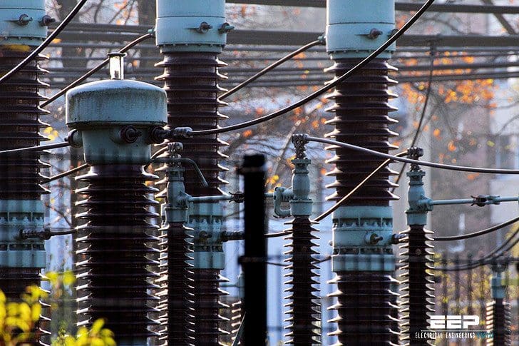
Generally speaking, you must agree that electrical power system is a complex project consisting of the four main ingredients. Now, let’s observe each ingridient in details:
1. Electricity supply
All countries now have available some supplies of electricity to connected consumers. In many industrialised countries a nationwide grid or distribution system is installed so that generating plant can be “pooled” through interconnections to supply customers from industrial/factory complexes down to the smallest residential consumer, perhaps with a single light or TV set.
Example is water pumped to a higher reservoir where the generating plant output must always match instantaneously the demand of the loads plus the losses (hopefully less than 10%) in transporting and delivering demanded energy (units of kWh).
For many good reasons, most small consumers require their supply at a low voltage (230 V in Europe, 110V in USA for example) whereas to keep losses low, electricity needs to be transmitted over any distance at a high voltage (400 kV in Europe, up to 700 kV in US/Canada).
Generation, on the other hand, is most economically done at around 20 kV thereby requiring a step-up in voltage to the transmission system and a step-down in voltage for distribution to the myriad of small (mainly residential) consumers.
This transformation is readily done by high efficiency transformers which require, due to Faraday’s law, an alternating voltage at 50 Hz in Europe, Japan, Australia, etc. and 60 Hz on the American continent. To keep material costs to a minimum, transmission and distribution is best done using a 3-phase system but only a single-phase supply is required by small consumers.
Large and intermediate consumers such as industrial processes, factories, large buildings and hospitals etc. are most economically supplied at a higher voltage than to small consumers, at between 10 to 20 kV.
Consequently, many distribution systems consisting of step-down transformers, cable or overhead lines operate at this voltage and only the final, comparatively short connections to individual small consumers, operate at 230V or 110 V, usually by tapping off from a 3-phase system.
Go back to power system ingridients list ↑
2. Transmission
Part of a typical generation and transmission network is depicted as a single line diagram as in Figure 1. It should be noted that generators are interconnected by a 3-phase system and it is essential that they run in synchronism with each other. If a generator cannot remain in synchronism due to a fault, then it must be disconnected by its circuit breaker otherwise the whole system could collapse.
Distribution systems are fed from the high voltage network through step-down transformers and increasingly there are smaller generators “embedded” in the distribution network adding to the combined energy output of the synchronised system.
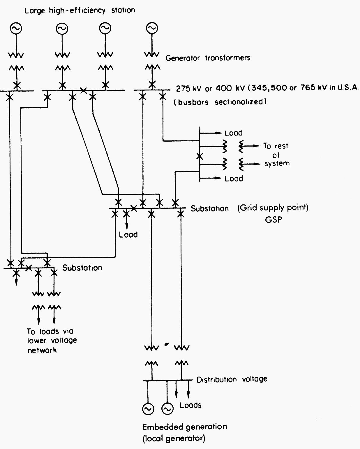

In a deregulated electricity supply industry (ESI), the generators could be owned and operated by different utilities, the transmission lines and substations owned by other investors and the supplies to the distribution systems bought under contract to private distributors or suppliers.
Increasingly, for undersea connections or for connections between networks not in synchronism, high voltage direct current using semiconductors as a rectifier one end and inverter the other is being used. Such connections should be considered as alternatives to a.c. connections.
Go back to power system ingridients list ↑
3. Distribution
Medium and low voltage distribution systems vary in their design and layout depending upon the locality being served. In urban areas, where consumers are numerous and concentrated, an underground network with closely spaced step-down transformer substations are installed sized to meet the maximum expected demand after taking into account the average diversity of customer use.
Figure 2 depicts a typical urban network where each single line represents 3 phases contained within a single under road cable.
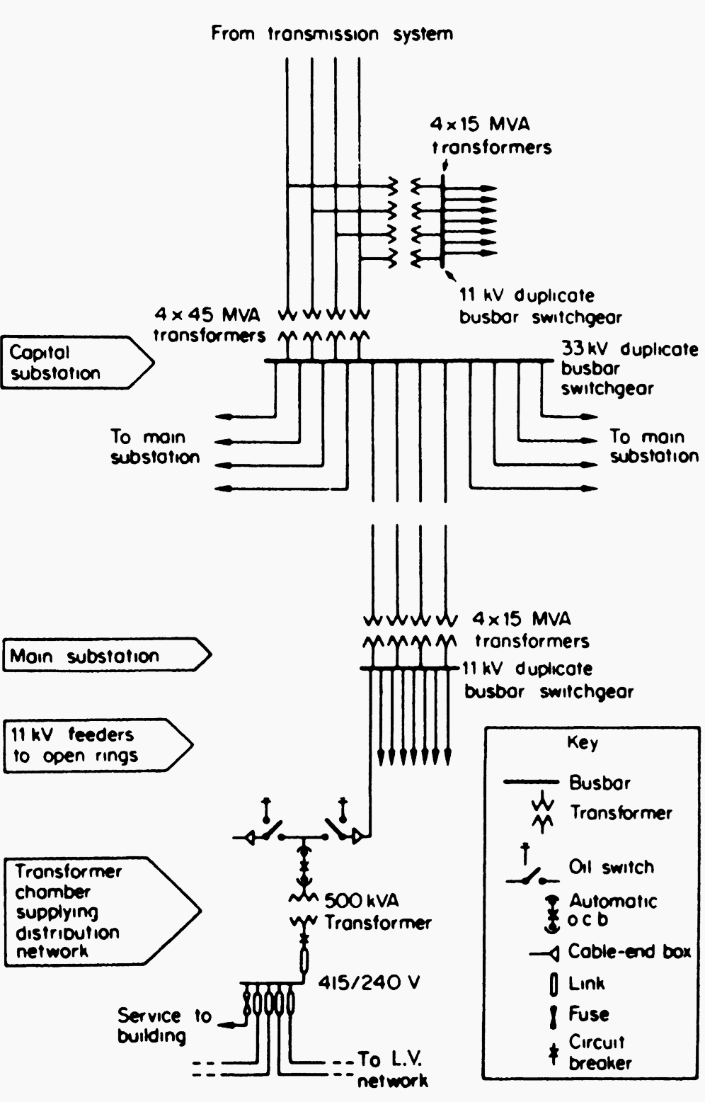

Because of the complexity of protecting the system if it was fully interconnected, it is usual to operate it as a radial system fed from the primary substations but allowing circuits to be supplied by alternative connections if any circuit is disconnected under fault or maintenance conditions.
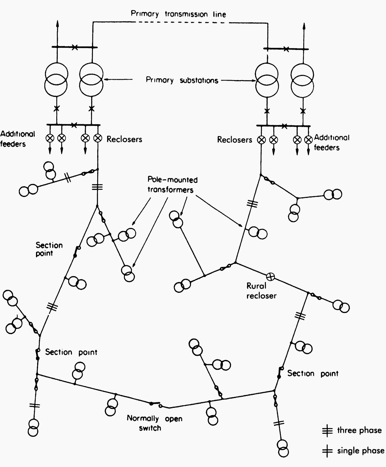
Figure 3 shows a typical rural distribution system in which section points allow manual re-switching to restore supplies after fuse disconnection. Overhead lines, either 3 phase or single phase, is the norm thereby allowing quick repair with a suitably equipped crew.

Go back to power system ingridients list ↑
4. Loads
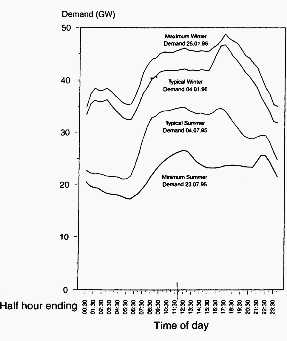
Consumer demand in a power system is often called a “load” and, of course, it will vary from hour to hour, day to day and season to season. Typical daily load curves aggregated over the whole England and Wales system are shown in Figure 4.
As previously remarked, the total generator output must match this demand and this requires the generators to be flexible.
At times when the demand is expected to fluctuate by 5% or so within minutes (as could happen in a countrywide event when kettles or cookers are switched on/off in co-ordination by a TV programme) then a number of generators, particularly those with quick response, will be scheduled.
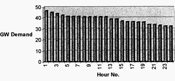
If the demand curve of Figure 4 is plotted in descending order of magnitude as in Figure 5, the resulting diagram depicts a duration curve. Over a year of operation this curve indicates the load factor at which various kinds of generating plant can be expected to operate.

Normally the plant having the cheapest price per kWh would operate at base load and the peaking plant would operate on very small load factor around the peak demand. Other plant, depending on its characteristics and production costs, would be expected to run at the intermediate load factors, probably generating during the day and shutting down at night (known as two shifting).

In interconnected systems or power pools where energy trading is allowed, the operation of the system is much more complex. In this case, existing generating plant may find that it is unable to rely on base or intermediate load operation and must be installed and run according to its contracted output portfolio rather than in any economic sense.
The availability of long term contracts on both the fuel supply side and the output energy side is likely to be the dominant feature of planning in the future.
Go back to power system ingridients list ↑
Reference // Electrical Engineer’s Reference Book by M. A. Laughton CEng., FIEE and D. J. Warne CEng., FIEE (Purchase hardcover from Amazon)


Excellent article for all the professionals those who are working in the field of power system. I have been following the articles for more than two years and greatly benefited in my professional career. Thanks a lot Edvard.
You’re welcome Tapan.
An excelent article. Thanks, Edvard!!
Regards,
Leonardo Cardillo
https://www.linkedin.com/in/leonardocardillo
You’re welcome Leonardo.
Thank you for these Sir edvard.
As an Electrical & Electronic Engineer (22 Years Experience ) I am using your technical information for last Three & Half Years. I am greatly benefited for my professional development. Well done
Thank you Manash!