


Estimated Study Time: 37 minutes
132kV Line Protection Panel Schematics
This article provides a comprehensive, sheet-by-sheet analysis of the Schneider Electric 132kV Line Protection Panel (Bay-B102) schematics. Moving beyond single-line abstractions, this technical review dissects the hard-wired DC control logic, safety interlocks, and tripping architectures explicitly documented in the engineering drawings.
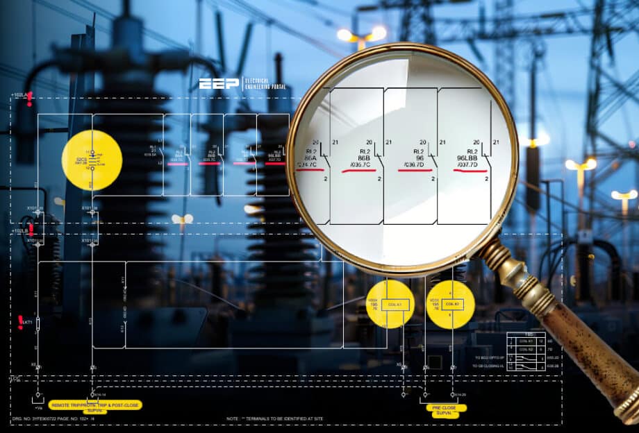 Inside the 132kV Line Bay: How Trip Relay Circuits Operate
The analysis maps the precise electrical pathways from initial fault detection by the primary distance (MiCOM P546) and backup directional earth-fault/overcurrent (MiCOM P143) numerical relays to the actuation of the high-speed master trip relays (86A, 86B, 96, and 96LBB).
Furthermore, it examines the integration of the Substation Automation System via the Bay Control Unit (C264), detailing the exact I/O assignments, terminal block allocations, and signal routing required to execute millisecond-level circuit breaker tripping, lockout configurations, and remote teleprotection protocols within a high-voltage GIS environment.
Grid coordinates (Page, Row, Column) are provided for precise traceability.
Here is the download link for the complete PDF document with drawings (85 pages). Open it up, so you can follow the discussion.
Schematics (PDF, 2.5 MB)
- Introduction to the Bay B102 Protection Scheme:
- The Trip Logic Matrix: From Fault to Execution:
- Powering the Trip Circuits: DC Distribution:
- Deep Dive: Master Trip Relay 86A (Group A):
- Deep Dive: Master Trip Relay 86B (Group B):
- Tracing the Busbar Trip Relay (96):
- Tracing the Local Breaker Backup Relay (96LBB):
- Translating Relays to Physical Action: The Trip Coil Circuits:
- Circuit Breaker Closing & Safety Interlocks
- The Bay Control Unit (BCU) Integration:
- Summary
- Attachment (PDF) 🔗 Relay Testing Guide: Overvoltage, Undervoltage, and Frequency Applications
1. Introduction to the Bay B102 Protection Scheme
In high-voltage transmission networks, a “Bay” refers to the switchgear and control equipment associated with a single circuit, in this case, 132kV Line-1. The protection panel for Bay B102 is designed with a philosophy of strict redundancy, reliability, and speed.
To achieve this, the panel utilizes two completely independent protection systems:
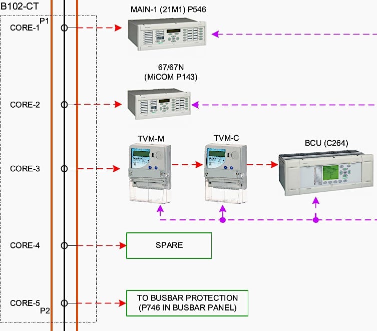
Main-1 Protection (21M1): This is handled by a Schneider Electric MiCOM P546 relay, which primarily provides distance protection (ANSI code 21), detecting the electrical distance to a fault.
Backup Protection (67/67N): This is handled by a Schneider Electric MiCOM P143 relay, providing Directional Overcurrent (67) and Directional Earth Fault (67N) protection.
When either of these relays detects an anomaly, they do not send a signal directly to the heavy-duty trip coils of the circuit breaker. Instead, they trigger intermediary devices known as Master Trip Relays or Lockout Relays (ANSI code 86).
Figure 1 – Main and Backup protection Systems (Main-1 MiCOM P546 & Backup MiCOM P143)
1.1 The Trip Relays of Bay B102
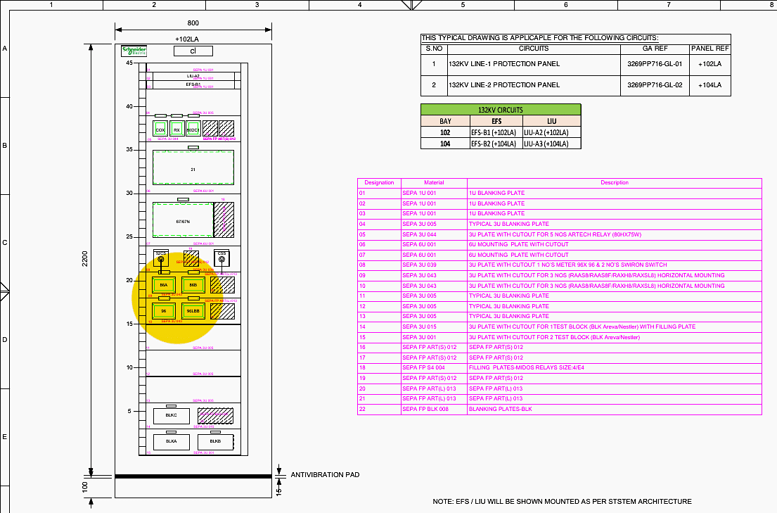
According to the Bill of Materials located on Sheet 002 and Sheet 006 of the attached PDF document, the panel employs four primary high-speed trip relays. All four are manufactured by Schneider Electric, bearing the part number GBINSEBAXBH8220.
The four specific relays are:
- 86A: Master Trip Relay – Group A
- 86B: Master Trip Relay – Group B
- 96: Busbar Trip Relay
- 96LBB: Local Breaker Backup (LBB) Trip Relay
Figure 2 – Trip Relays of Bay B102
2. The Trip Logic Matrix: From Fault to Execution
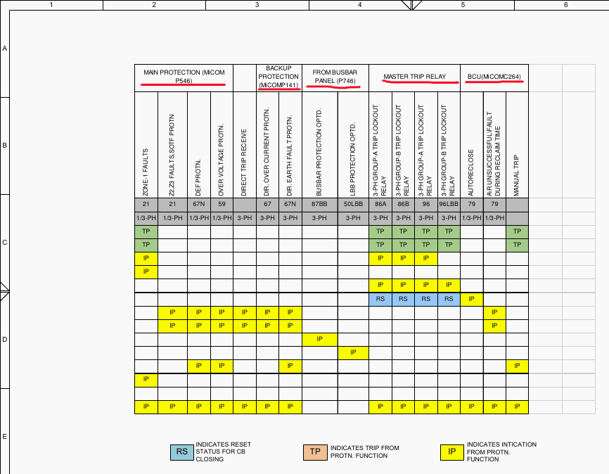
Before tracing the physical wiring, it is crucial to understand the logical architecture that dictates which fault triggers which relay. This is explicitly detailed on Sheet 003: Trip Logic. This matrix is the brain of the panel’s protection scheme.
2.1 Main Protection (MiCOM P546) Initiations
The 21M1 relay monitors the line for several specific fault types. If it detects a fault, it operates internal output contacts that send 220V DC to the trip relays. According to Sheet 003:
Zone-1 Faults: A severe fault close to the substation. The P546 will initiate a 1-phase or 3-phase trip. It sends a Trip Pulse (TP) to both the 86A and 86B trip relays, as well as an Indication Pulse (IP) to the Bay Control Unit (BCU).
Z2, Z3 FAULTS, SOTF PROTN (Switch On To Fault): Faults further down the line or faults that occur the moment the breaker is closed. These trigger a strict 3-phase trip, operating both 86A and 86B.
DEF PROTN (Directional Earth Fault): Triggers a 3-phase trip via 86A and 86B.
OVER VOLTAGE PROTN (59): Triggers a 3-phase trip via 86A and 86B.
2.2 Backup Protection (MiCOM P143) Initiations
The 67/67N relay acts as a fail-safe. If the main protection fails, or if a specific overcurrent/earth fault is detected, this relay takes action. According to Sheet 003:
DIR. OVER CURRENT PROTN: Triggers a 3-phase trip. Crucially, to maintain strict circuit segregation, the Backup protection only initiates the 86B trip relay. It does not trigger 86A.
DIR. EARTH FAULT PROTN: Similarly, this triggers a 3-phase trip solely through the 86B trip relay.
2.3 External System Initiations
The panel also reacts to commands from outside its own bay.
DIRECT TRIP RECEIVE: If a remote substation detects a fault and sends a teleprotection signal via the Power Line Carrier Communication (PLCC) system, the RX relay in Bay B102 activates. This triggers a 3-phase trip via both 86A and 86B.
BUSBAR PROTECTION OPTD (87BB): If a fault occurs on the busbar itself (detected by the P746 relay in the dedicated Busbar Panel), a signal is sent to Bay B102, which operates the 96 Busbar Trip Relay.
LBB PROTECTION OPTD (50LBB): If the circuit breaker fails to open when commanded, the Local Breaker Backup scheme operates, triggering the 96LBB relay.
Figure 3 – Trip Logic Matrix for MiCOM P546, MiCOM P143 and External Faults
3. Powering the Trip Circuits: DC Distribution
A protection relay cannot trip a breaker without reliable power. High-voltage substations use heavy-duty DC battery banks because DC power is immune to the AC grid collapsing during a fault. The Bay B102 panel utilizes a 220V DC system, heavily segregated for reliability.
3.1 DC Source-1
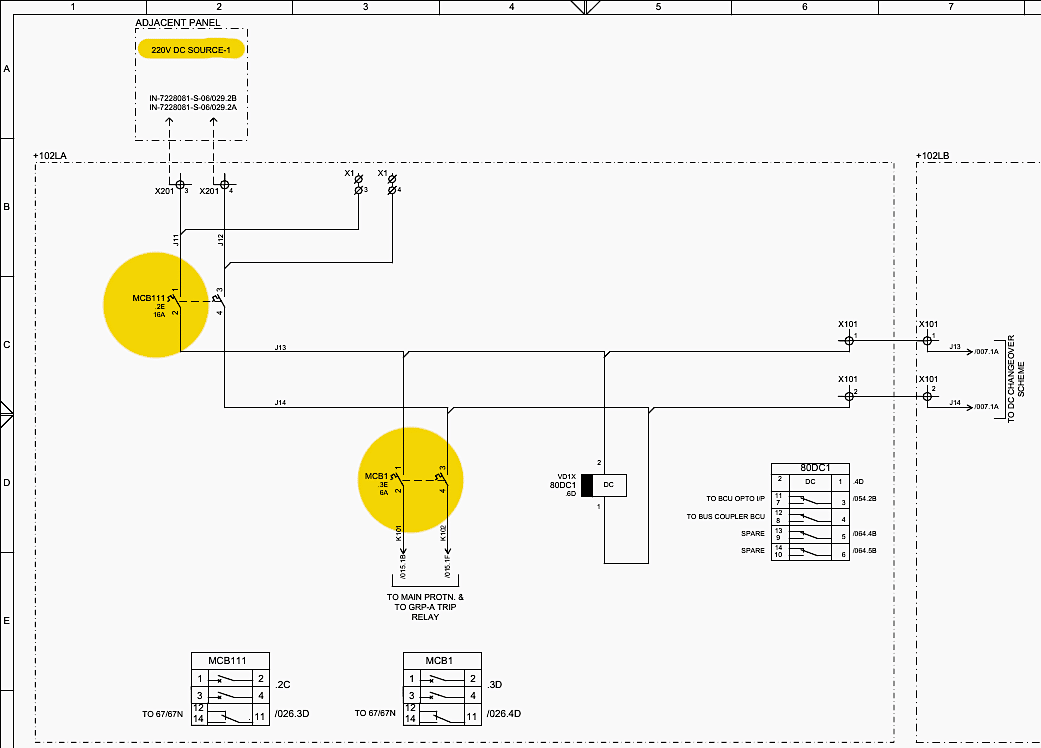
According to Sheet 005 (DC Distribution CKT), 220V DC Source-1 enters the panel through a 16A double-pole Miniature Circuit Breaker (MCB) designated as MCB111. The positive leg of this circuit is routed through a secondary 6A MCB MCB1 to power the Main-1 protection circuits.
Row 3, Column D (Sheet 005.3D): The positive voltage (ferrule K101) is routed to the MiCOM P546 relay and the Group-A Master Trip Relay (86A).
Row 1, Column B (Sheet 015.1B): The K101 positive voltage arrives at the Distance Protection AC/DC input circuits, waiting to be switched by the relay’s internal logic.
Figure 4 – DC Source-1
3.2 DC Source-2
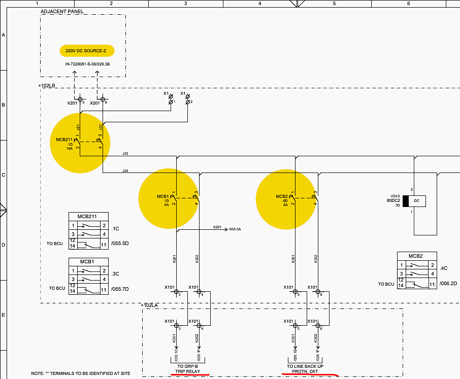
For total redundancy, a completely independent battery bank, 220V DC Source-2, is utilized. As shown on Sheet 006 (DC Distribution CKT), this enters via a 16A MCB designated MCB211. The power is further distributed:
Row 6, Column D (Sheet 006.6D): A 6A breaker MCB2 routes the positive DC voltage (ferrule K301) specifically to the Line Backup Protection Circuit (P143 relay).
Row 3, Column D (Sheet 006.3D): The positive voltage (ferrule K201) is routed to the Group-B Master Trip Relay (86B).
This strict segregation means that if Battery Bank 1 fails, or if MCB1 trips, the Main protection (21M1) and 86A will die, but DC Source-2 will seamlessly keep the Backup protection (67/67N) and 86B alive, ensuring the breaker can still be tripped.
Figure 5 – DC Source-2
4. Deep Dive: Master Trip Relay 86A (Group A)
The 86A relay is the primary executioner for the Main-1 protection system. Its internal wiring and contact distribution are exhaustively mapped out on Sheet 034: GROUP-A TRIP RELAY CKT.
4.1 Activating the 86A Coil
For the 86A relay to actuate, its operating coil, labeled OP, must be energized.
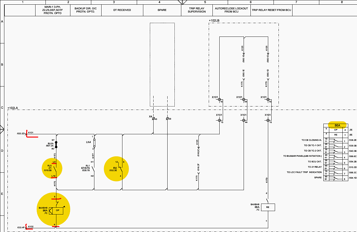
- Locating the Coil: On Sheet 034, Row 7, Column C (034.7C), the operating coil of 86A is depicted. It has two terminal inputs: ‘a’ (positive) and ‘b’ (negative).
- The Negative Path: Terminal ‘b’ is permanently tied to the negative DC bus (ferrule K102).
- The Positive Path: Terminal ‘a’ requires the positive 220V DC (ferrule K101) to complete the circuit. This positive voltage is sitting at the internal output contacts of the Main-1 relay (MiCOM P546).
- The Trigger: As detailed on Sheet 019, Row 5, Column B (019.5B), output relay RL5 of the P546 is designated for triggering 86A.If the P546 detects a 3-Phase fault, Zone 2, Zone 3, Overvoltage, DEF, or SOTF condition, it closes contact RL5.
- The Circuit Completes: The closure of RL5 bridges terminals L9 and L10 on the P546 relay. The positive K101 voltage flows out of terminal L10, through a link block, and directly into terminal ‘a‘ of the 86A coil (Sheet 034.7C).
- Direct Trip Integration: Alternatively, if a direct trip is received from a remote substation, the RX carrier receive relay operates. On Sheet 032, Row 3, Column E (032.3E), the RX relay’s normally open contact (terminals 8-4-12) closes. This contact is wired in parallel with the P546 RL5 contact. Therefore, the RX relay closing also sends positive voltage to the 86A coil.
Figure 6 – Activating the 86A Coil
4.2 The Output Actions of 86A
Once the 86A coil energizes, its electromagnetic armature pulls in, flipping all 8 of its changeover contacts simultaneously in a fraction of a millisecond. These contacts are distributed across the panel to execute the trip and block dangerous operations.
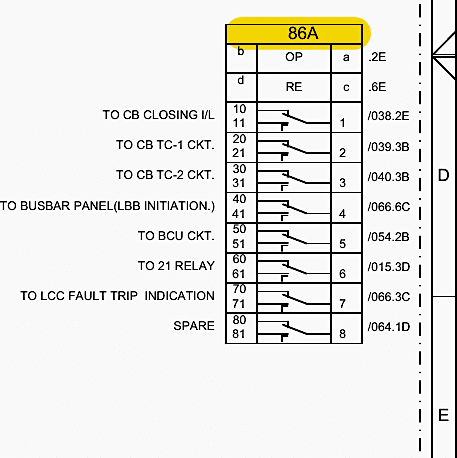
According to the contact mapping table on Sheet 034, the 8 contacts (each having a common, normally open, and normally closed terminal) perform the following tasks:
Contact 1 (Terminals 11, 1, 10) – CB Closing Interlock
Destination: Sheet 038, Row 2, Column E (038.2E).
Function: This uses the Normally Closed (NC) contact (11 and 1). When 86A trips, this contact opens. This breaks the positive DC supply (ferrule K21) to the Circuit Breaker Closing circuit.
Contact 2 (Terminals 21, 2, 20) – Trip Coil-1 (TC-1) Energization
Destination: Sheet 039, Row 3, Column B (039.3B).
Function: This uses the Normally Open (NO) contact (21 and 2). When 86A operates, this contact closes. It takes the positive DC voltage from the 52CS (CB Control Switch) and passes it down to energize the physical Trip Coil 1 inside the high-voltage circuit breaker out in the switchyard, forcing the primary contacts open.
Contact 3 (Terminals 31, 3, 30) – Trip Coil-2 (TC-2) Energization
Destination: Sheet 040, Row 3, Column B (040.3B).
Function: Using the NO contact (31 and 3), 86A also sends a parallel trip command to the secondary trip coil (TC-2) of the circuit breaker. This ensures that even if TC-1 fails mechanically, the breaker will still open.
Contact 4 (Terminals 41, 4, 40) – LBB Initiation to Busbar Panel
Destination: Sheet 066, Row 6, Column C (066.6C).
Function: Using the NO contact, a signal is sent out of Bay B102, through inter-panel bus wiring (terminal X201), to the Busbar Protection Panel. This initiates the Local Breaker Backup timer.
Contact 5 (Terminals 51, 5, 50) – BCU Event Logging
Destination: Sheet 054, Row 2, Column B (054.2B).
Function: The NO contact closes to send a 220V signal to Digital Input Channel 3 (DI3) on SLOT-N of the Bay Control Unit (C264). This allows the Substation Automation System (SAS) to log exactly when the 86A relay operated, time-stamped to the millisecond.
Contact 6 (Terminals 61, 6, 60) – Feedback to 21M1 Relay
Destination: Sheet 015, Row 3, Column D (015.3D).
Function: The NO contact provides a status feedback loop into the P546 distance relay.
Contact 7 (Terminals 71, 7, 70) – LCC Fault Trip Indication
Destination: Sheet 066, Row 3, Column C (066.3C).
Function: The NO contact sends a signal to the Local Control Cubicle (LCC) located out in the switchyard next to the physical breaker, illuminating a “Fault Trip” warning lamp.
Contact 8 (Terminals 81, 8, 80) – Spare
Destination: Sheet 064, Row 1, Column D (064.1D). Left unwired for future expansion.
Figure 7 – Output Actions of 86A
4.3 Resetting the 86A Relay
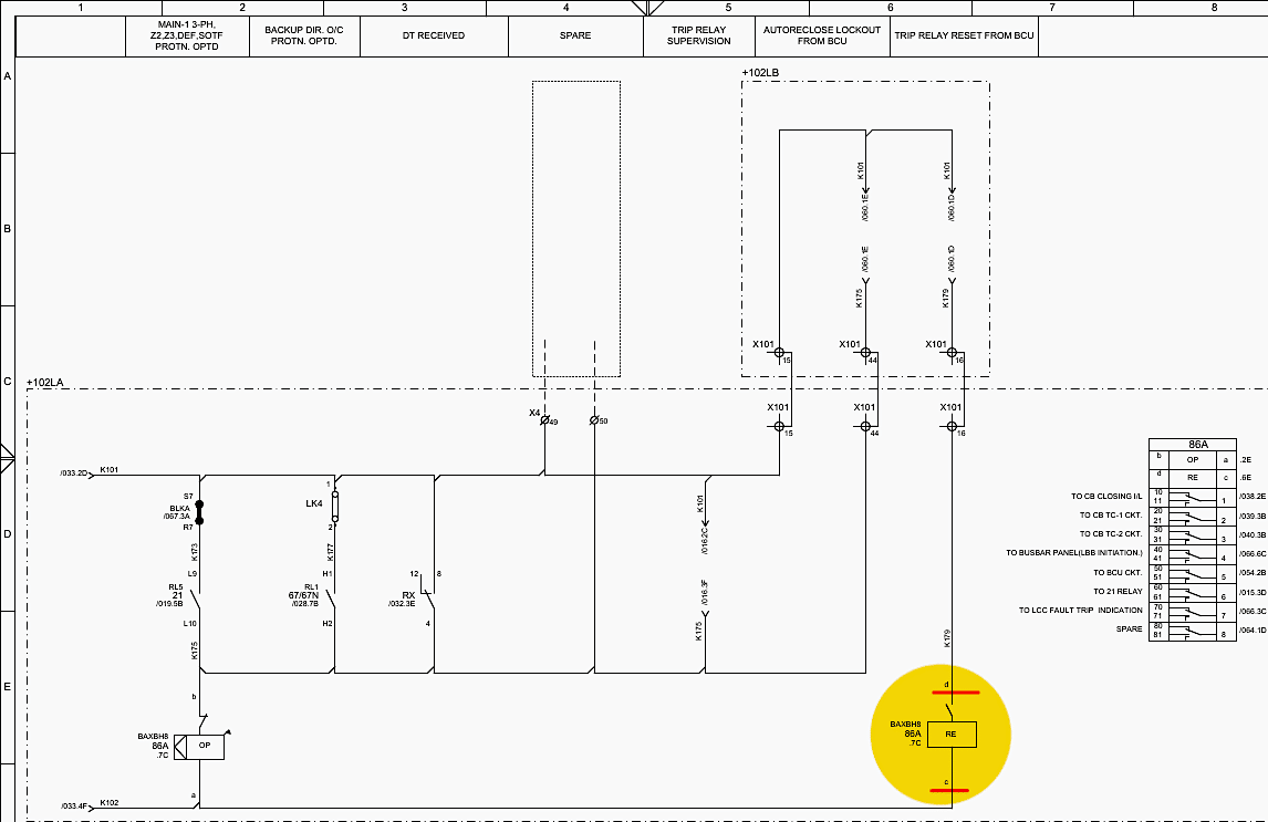
Because 86A is a “Lockout” relay, once it operates, it mechanically latches in the trip position. The breaker cannot be closed until 86A is reset. According to the attached PDF schematics on Sheet 034, Row 6, Column E (034.6E), the relay features an electrical reset coil RE.
The Reset coil receives negative DC on terminal ‘d‘. The positive trigger for terminal ‘c‘ comes from the Bay Control Unit (BCU).
This voltage travels to Sheet 034.6B, energizing the reset coil (‘c‘), forcing the mechanical latch to release, and returning the 86A relay to its normal state.
Figure 8 – Resetting the 86A Relay
5. Deep Dive: Master Trip Relay 86B (Group B)
The 86B Master Trip Relay provides absolute redundancy. Even if the entire 86A relay circuit is faulted, 86B can isolate the fault. Its wiring is detailed on Sheet 035: GROUP-B TRIP RELAY CKT.
5.1 Activating the 86B Coil
The 86B operating coil (terminals ‘a‘ and ‘b‘) is located at Sheet 035, Row 7, Column C (035.7C). It relies on DC Source-2 (ferrules K201 for positive, K202 for negative). The trigger mechanisms are far more varied than 86A:
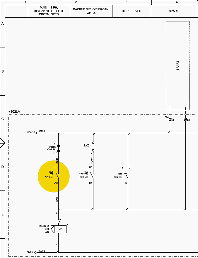
1. Main Protection Trigger: On Sheet 019, Row 5, Column B (019.5B), the P546 relay operates contact RL6. This contact closes to send the K201 positive voltage to the 86B coil. This guarantees that if the Main protection sees a fault, it fires both 86A and 86B simultaneously.
Figure 9 – Main Protection Trigger
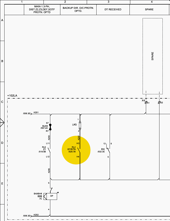
2. Backup Protection Trigger: On Sheet 028, Row 7, Column B (028.7B), the Backup MiCOM P143 relay operates contact RL2. If the P143 detects a Directional Overcurrent or Earth Fault, RL2 closes. This takes K201 positive voltage and routes it to 86B (Sheet 035.7C).
3. Direct Trip Integration: On Sheet 032, Row 3, Column E (032.3E), a second contact on the RX teleprotection relay (terminals 13-5-9) is wired. When a remote trip is received, this contact closes, routing K201 positive voltage to 86B.
Figure 10 – Backup Protection Trigger
5.2 The Output Actions of 86B
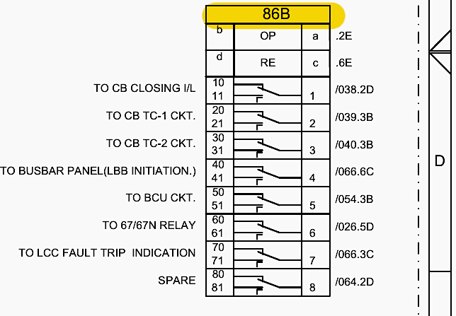
When energized, the 8 contacts of the 86B relay operate almost identically to 86A, providing parallel paths to critical endpoints, as outlined on Sheet 035:
- Contact 1 (11, 1, 10): CB Closing Interlock. Routes to Sheet 038.2D. It is wired in series with the 86A contact. If either 86A or 86B is tripped, the closing circuit is blocked.
- Contact 2 (21, 2, 20): Trip Coil-1 (TC-1). Routes to Sheet 039.3B, wired in parallel with 86A to ensure TC-1 fires.
- Contact 3 (31, 3, 30): Trip Coil-2 (TC-2). Routes to Sheet 040.3B, wired in parallel with 86A to ensure TC-2 fires.
- Contact 4 (41, 4, 40): LBB Initiation. Routes to Sheet 066.6C to start the breaker failure timer in the busbar panel.
- Contact 5 (51, 5, 50): BCU Event Logging. Routes to Sheet 054.3B. It triggers a unique Digital Input (DI4) on the BCU so the SCADA system knows specifically that Group B operated.
- Contact 6 (61, 6, 60): Feedback to 67/67N Relay. Routes to Sheet 026.5D, providing status feedback to the Backup P143 relay.
- Contact 7 (71, 7, 70): LCC Fault Trip Indication. Routes to Sheet 066.3C.
- Contact 8 (81, 8, 80): Spare. Routes to Sheet 064.2D.
Figure 11 – Output Actions of 86B
5.3 Resetting the 86B Relay
Resetting 86B utilizes the identical architecture as 86A. The reset coil (Sheet 035.6E) is commanded by the BCU. Specifically, the BCU Digital Output Card (SLOT-E), contact DO6 (Sheet 061.3B), sends a 220V DC pulse to electrically unlatch the 86B mechanism.
6. Tracing the Busbar Trip Relay (96)
While 86A and 86B protect the 132kV transmission line extending out of the substation, the 96 Busbar Trip Relay responds to catastrophic faults within the substation itself. If the HV busbar that connects all the bays experiences a short circuit, the dedicated Busbar Protection Panel issues a blanket trip command to every single bay connected to that bus to isolate the fault.
6.1 Activating the 96 Relay
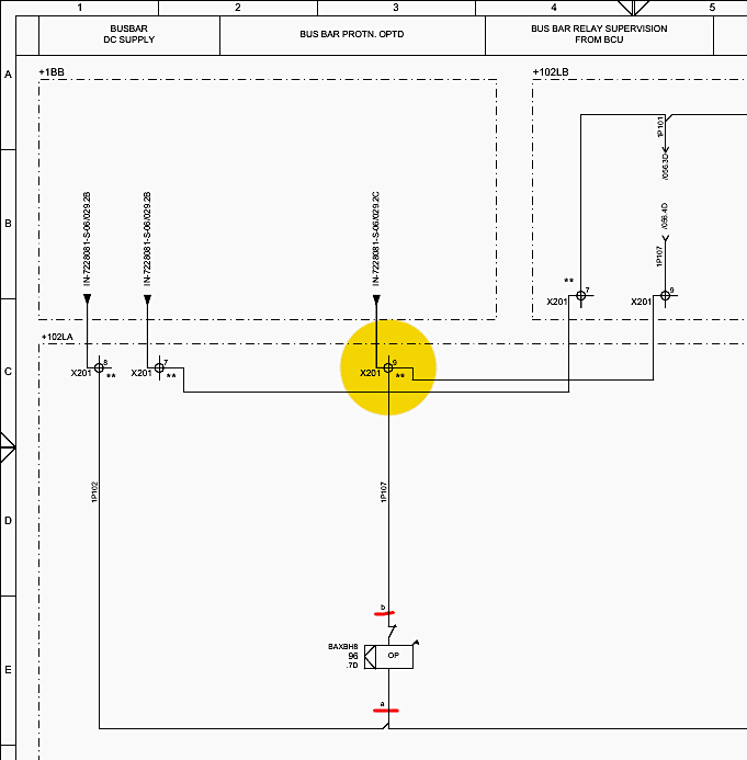
Detailed on Sheet 036: BUSBAR TRIP RELAY CKT, the 96 relay’s operating coil is located at Zone 7D. Unlike 86A/B, the trigger does not come from the relays inside this panel. Instead, the command originates from the external Busbar Panel (+1BB).
A positive 220V DC signal (ferrule 1P107) travels from the Busbar panel, through inter-panel terminal block X201 (terminal 9), as shown on Sheet 036, Row 3, Column C (036.3C). This signal directly energizes the ‘a‘ terminal of the 96 operating coil.
Figure 12 – Activating the Busbar Trip Relay (96)
6.2 Output Actions of the 96 Relay
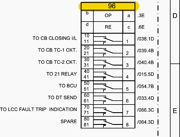
Because a busbar fault is highly critical, the 96 relay executes an immediate lockdown of the breaker. Its contact configuration (listed on Sheet 036) is:
- Contact 1 (11, 1, 10): CB Closing Interlock. Routes to Sheet 038.1D. It breaks the closing circuit series chain, ensuring the breaker cannot be closed back onto a faulted busbar.
- Contact 2 (21, 2, 20): Trip Coil-1 (TC-1). Routes to Sheet 039.4B, parallel to 86A/B, to execute the physical trip.
- Contact 3 (31, 3, 30): Trip Coil-2 (TC-2). Routes to Sheet 040.4B, parallel to 86A/B, ensuring redundant trip execution.
- Contact 4 (41, 4, 40): Feedback to 21M1 Relay. Routes to Sheet 015.5D.
- Contact 5 (51, 5, 50): BCU Event Logging. Routes to Sheet 054.7B, alerting the SCADA system of a busbar trip via Digital Input DI7.
- Contact 6 (61, 6, 60): Direct Trip Send. Routes to Sheet 033.4D. If the busbar is faulted, this panel must send a teleprotection carrier signal to the far-end substation to trip their breaker as well, isolating the line from the other side.
- Contact 7 (71, 7, 70): LCC Indication. Routes to Sheet 066.3C.
- Contact 8 (81, 8, 80): Spare. Routes to Sheet 064.3D.
Figure 13 – Output Actions of the 96 Relay
7. Tracing the Local Breaker Backup Relay (96LBB)
The ultimate nightmare scenario in a substation is a “stuck breaker“, the protection relays issue a trip command, the trip coils energize, but the mechanical linkages inside the circuit breaker are jammed, and high fault current continues to flow.
The Local Breaker Backup (LBB) scheme resolves this.
7.1 Activating the 96LBB Relay
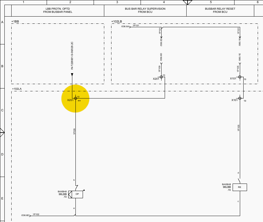
The circuit is documented on Sheet 037: LBB TRIP RELAY CKT.
If the 86A or 86B relays operate, they start a timer in the Busbar Protection Panel (via their Contact 4). If current continues to flow through the CTs of Bay B102 after 200ms, the Busbar panel assumes breaker B102 is stuck.
The Busbar panel will trip all other breakers on the bus. Simultaneously, it sends an LBB trip command back to Bay B102 as a final attempt to clear the local breaker. This signal arrives via ferrule 1P109 through terminal block X201 (terminal 10), shown on Sheet 037, Row 2, Column C (037.2C).
This energizes the operating coil of 96LBB located at Sheet 037.7D.
Figure 14 – Activating the 96LBB Relay
7.2 Output Actions of the 96LBB Relay
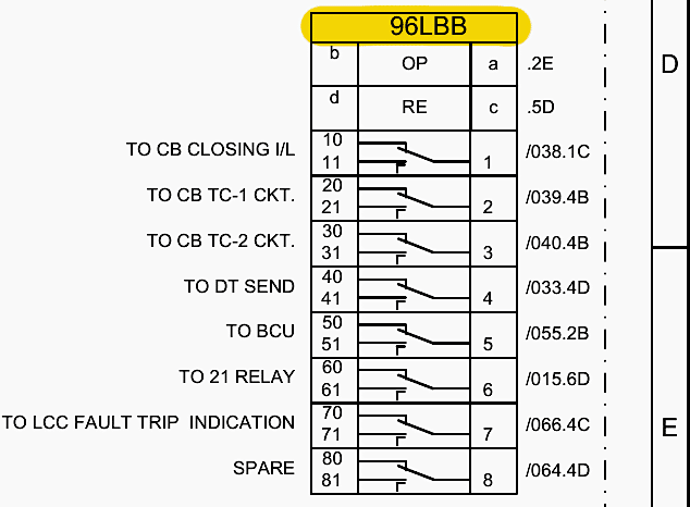
The outputs mirror the posture of the 96 Busbar relay:
- Contact 1 (11, 1, 10): CB Closing Interlock: Routes to Sheet 038.1C, placing a hard block on any closing attempts.
- Contact 2 (21, 2, 20): Trip Coil-1 (TC-1): Routes to Sheet 039.4B.
- Contact 3 (31, 3, 30): Trip Coil-2 (TC-2): Routes to Sheet 040.4B.
- Contact 4 (41, 4, 40): Direct Trip Send: Routes to Sheet 033.4D to inform the remote end to open its breaker immediately because the local breaker has failed.
- Contact 5 (51, 5, 50): BCU Event Logging: Routes to Sheet 055.2B.
- Contact 6 (61, 6, 60): Feedback to 21M1 Relay: Routes to Sheet 015.6D.
- Contact 7 (71, 7, 70): LCC Indication: Routes to Sheet 066.4C.
Figure 15 – Output Actions of the 96LBB Relay
8. Translating Relays to Physical Action: The Trip Coil Circuits
All the complex logic of the protection relays (P546, P143) and the high-speed switching of the trip relays (86A, 86B, 96, 96LBB) ultimately converge in two places: The Trip Coil 1 (TC-1) and Trip Coil 2 (TC-2) circuits.
8.1 The CB TC-1 Control Circuit (Sheet 039)
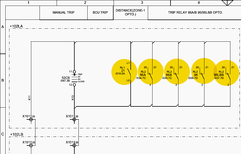
Sheet 039 details the final mile of the primary tripping mechanism. The circuit receives positive 220V DC from the Local/Remote selector switch (ferrule K21). In the middle of the sheet (Zones 3B to 4B), we see a parallel ladder logic structure. The Normally Open (NO) contacts of 86A (terminals 20-2-21), 86B (terminals 20-2-21), 96 (terminals 20-2-21), and 96LBB (terminals 20-2-21) are wired here side-by-side.
If any single one of those contacts closes, the positive DC voltage bridges across the gap.
The electromagnetic force of the coil strikes a physical latch, allowing mechanical springs to forcefully pull the high-voltage contacts apart, extinguishing the 132kV arc and isolating the fault.
Figure 16 – CB TC-1 Control Circuit (Sheet 039)
8.1.1 Trip Circuit Supervision (195):
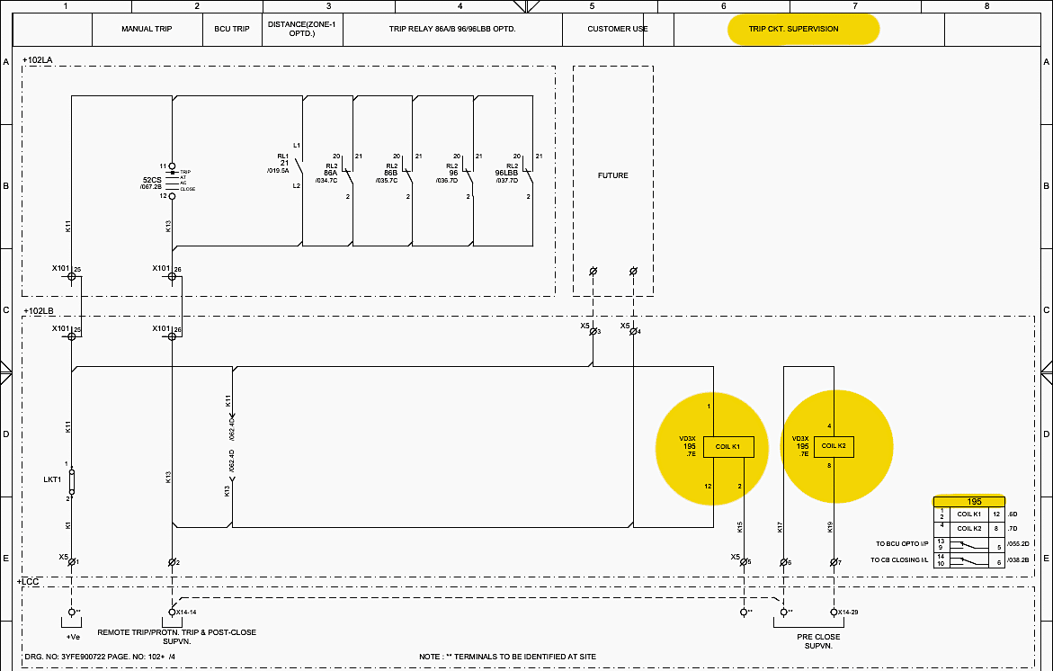
To ensure the trip coil wire isn’t broken, the 195 TC-1 Supervision Relay constantly monitors the circuit. As shown on Sheet 039.6D and 039.7D, the 195 relay utilizes two internal coils (K1 and K2). When the breaker is closed, a tiny, harmless trickle of current flows through the trip coil and through the 195 coils, keeping them energized.
If the physical wire to the trip coil is severed, the trickle current stops, the 195 coils drop out, and an alarm is instantly generated to the BCU indicating “CB TC-1 FAULTY” (routed via ferrule S119 to BCU DI13 on Sheet 056.2D).
Figure 17 – Trip Circuit Supervision (195)
8.2 The CB TC-2 Control Circuit (Sheet 040)
Sheet 040 is a near-identical mirror of Sheet 039, dedicated entirely to the secondary trip coil (TC-2). It operates off DC Source-2, maintaining the strict segregation from Group A. The parallel array of NO contacts from 86A, 86B, 96, and 96LBB (terminals 30-3-31) sit ready to bridge the gap.
If a trip is initiated, voltage flows out through terminal block X5 (terminals 10 and 8)** to physical Trip Coil 2 in the switchyard. The circuit is continuously monitored by the 295 TC-2 Supervision Relay, functioning exactly like the 195 relay.
9. Circuit Breaker Closing & Safety Interlocks
While the ability to trip a breaker instantly is paramount, preventing a breaker from closing onto a known fault is equally critical. The trip relays (86A, 86B, 96, 96LBB) not only execute the trip but also mechanically lock out the closing circuit.
This architecture is found on Sheet 038: CB CLOSING & REMOTE TRIP-1 CIRCUIT.
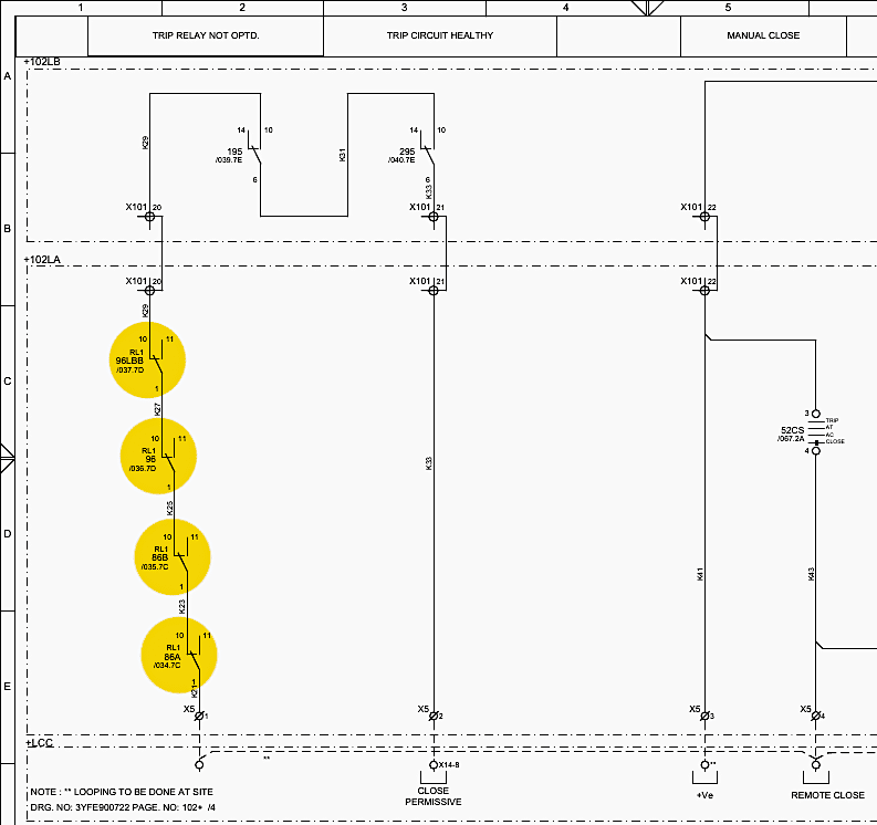
The Normally Closed (NC) contacts of the trip relays are wired in series: 86A (10-1-11) -> 86B (10-1-11) -> 96 (10-1-11) -> 96LBB (10-1-11). Under normal, healthy conditions, all these relays are at rest, their NC contacts remain closed, and the voltage passes through safely, allowing the breaker to be closed.
If a fault occurs and, for example, 86A operates, its 10-1-11 contact snaps open. The series chain is instantly broken. The closing circuit loses all positive potential.
No amount of manual overriding or SCADA commands can close the breaker until the fault is physically investigated and the 86A relay is manually or electrically reset to restore the series connection.
Figure 18 – Circuit Breaker Closing & Safety Interlocks
10. The Bay Control Unit (BCU) Integration
The Schneider Electric C264 Bay Control Unit acts as the centralized brain for Substation Automation and SCADA interfacing within Bay B102. It is explicitly detailed across multiple sheets of attached (PDF) schematics, specifically regarding how it interacts with the trip relay circuits.
10.1 Event Monitoring via Digital Inputs (DIU)
The BCU must know the exact millisecond a trip relay operates to construct accurate sequence-of-events records. It does this via Digital Input Unit (DIU) cards.
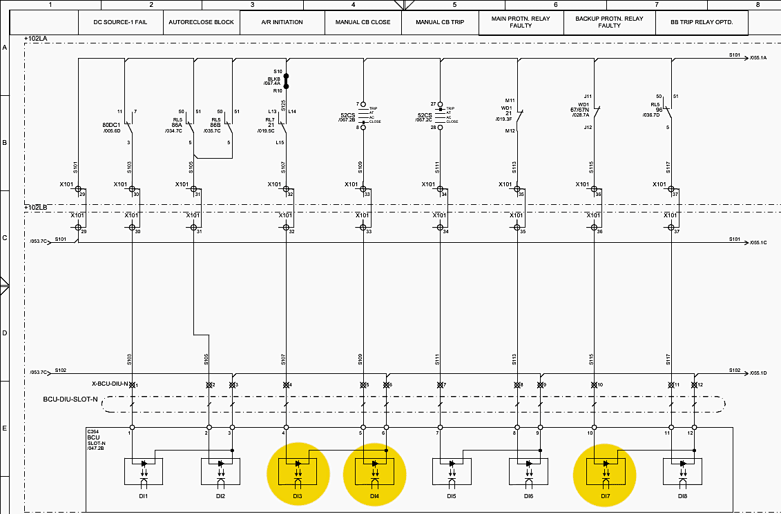
Sheet 054 (BCU-DIU-SLOT-N): As previously traced, the positive DC signal from the NO contacts of 86A, 86B, 96, and 96LBB are wired into this card.
- DI3 (ferrule S103): Registers Group-A (86A) operations.
- DI4 (ferrule S105): Registers Group-B (86B) operations.
- DI7 (ferrule S115): Registers Busbar (96) operations.
- DI9 (ferrule S123): Registers LBB (96LBB) operations.
Figure 19 – Event Monitoring via Digital Inputs (DIU)
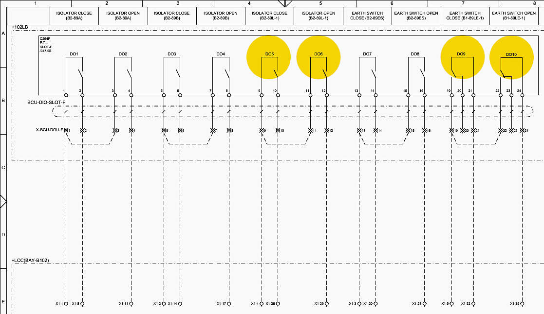
10.2 Command Execution via Digital Outputs (DOU)
Conversely, the SCADA system operator relies on the BCU to issue commands to the panel, specifically to reset the mechanical trip relays once a fault is cleared. This uses the Digital Output Unit (DOU) cards.
Sheet 060 and Sheet 061 (BCU-DIO-SLOT-E): When the operator issues a reset command, the C264 closes designated internal output contacts.
- DO5 (ferrule K179): Closes to send 220V DC to the electrical reset coil of 86A (Sheet 034.6B).
- DO6 (ferrule K209): Closes to send 220V DC to the electrical reset coil of 86B (Sheet 035.6B).
- DO9 (ferrule 1P103): Closes to send an inter-panel reset command through X201 to reset the Busbar relay 96 (Sheet 036.6B).
- DO10 (ferrule 1P105): Closes to send an inter-panel reset command through X201 to reset the LBB relay 96LBB (Sheet 037.5B).
Figure 20 – Command Execution via Digital Outputs (DOU)
11. Summary
The trip relay circuits inside the 132kV Line-1 Protection Panel (Bay B102) represent a masterpiece of redundant electrical engineering. By relying on two independent 220V DC sources, isolated Main and Backup protection relays (MiCOM P546 and P143), and the deployment of duplicated, high-speed master trip relays (86A and 86B) alongside specialized Busbar (96) and LBB (96LBB) relays, the system ensures infallible operation.
From the initial detection of a phase-to-earth fault by the P546 relay, to the microsecond bridging of the 86A contacts, to the violent energization of Trip Coil 1, the design guarantees that the Chambi GIS Substation can instantly extinguish catastrophic faults, protecting both the infrastructure and the stability of the entire high-voltage grid.
12. Attachment (PDF): Relay Testing Guide: Overvoltage, Undervoltage, and Frequency Applications
Download: Relay Testing Guide: Overvoltage, Undervoltage, and Frequency Applications (for premium members only):
Related electrical guides & articles



Edvard Csanyi
Hi, I'm an electrical engineer, programmer and founder of EEP - Electrical Engineering Portal. I worked twelve years at Schneider Electric in the position of technical support for low- and medium-voltage projects and the design of busbar trunking systems.I'm highly specialized in the design of LV/MV switchgear and low-voltage, high-power busbar trunking (<6300A) in substations, commercial buildings and industry facilities. I'm also a professional in AutoCAD programming.
Profile: Edvard Csanyi