Capacitor banks do need maintenance…
Capacitor banks generally require very little maintenance because they are static type of equipment, but don’t be fooled by this statement. Capacitors are well known for their dangerous reaction when something goes wrong.

Standard safety practices should be followed during installation, inspection, and maintenance of capacitors. Additionally, there are procedures that are unique to capacitor banks that must be followed to protect field operators and equipment in accordance with the NESC – National Electrical Safety Code.
Ok, let’s describe eight most important practices in inspection and maintenance of capacitor banks:
1. Clearance and Grounding
After a capacitor bank is de-energized, there will be residual charges in the units. Therefore, wait at least 5 min before approaching it to allow sufficient time for the internal discharge resistors in each capacitor unit to dissipate the stored energy.
These resistors are designed to reduce the voltage across the individual capacitor units to less than 50 V within 5 minutes.
Even after grounding, it is recommended that individual capacitor units be shorted and grounded before personnel come into contact with them to ensure that no stored energy is present.
2. Bulged Capacitor Units
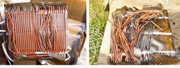
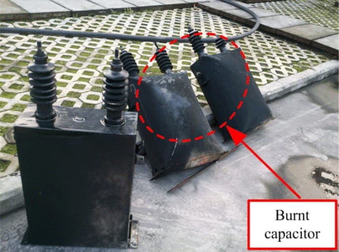
One of the failure modes of capacitor units is bulging. Excessively bulged units indicate excessive internal pressure caused by overheating and generation of gases due to probable arcing condition. These units should be handled carefully.
The manufacturer should be consulted regarding the handling of bulged units.


3. Leaking from Capacitor Units
Another mode of failure in the capacitor bank is leaking due to the failure of the cans. When handling the leaking fluid, avoid contact with the skin and take measures to prevent entry into sensitive areas such as eyes.
Handling and disposal of capacitor insulating fluid should comply with state, federal, and local regulations.
Some capacitor units contain combustible liquid and require careful handling.
4. Re-Energization of the Capacitor Banks
When returning to service, verify that all ground connections that were installed for maintenance purpose are removed.
Allow a minimum of 5 min between de-energization of the capacitor bank and re-energization of the capacitor bank to allow enough time for the stored energy to dissipate.


5. Initial Inspection Measurements and Energization Procedures
During the initial inspection before energization of the capacitor banks the following measures should be taken:
Measure #1 – Verify proper mechanical assembly of the capacitor units, clearances as per the electrical code, and soundness of the structure of all capacitor banks.
Measure #2 – It may be useful to measure the capacitance of the banks and keep the measurements as benchmark data for future comparison.
Measure #3 – Check the electrical connections for proper installation and good electrical contact. Verify that all terminal connections are tightened properly.
Check the individual fuse connections to ensure that they are tight and make good contact.
Measure #4 – Clean all insulators, fuses, and bushings to prevent the possibility of dirty porcelain creating a flashover danger. Inspect all porcelain insulators for cracks or breaks.
Measure #5 – Test the operation of all controls and load break, disconnect, and grounding switches prior to energizing the capacitor banks.
Measure #6 – Prior to energizing the bank, verify the capacitance values of each phase and compare them with the coordination values used in the relay settings.
The capacitance unbalance should not result in a voltage of more than 110% of the rated voltage on any one unit.
Measure #7 – Immediately after energization, verify the voltage increase on the terminals and compare it with the calculated values.
Also, measure and verify if the supply voltage, phase currents, and the kVAR of the capacitor bank are within the allowed limits.
6. Periodic Inspection, Measurement, and Maintenance
The substation and distribution capacitor banks should be inspected and electrical measurements be made periodically.
The frequency of the inspection should be determined by local conditions such as environmental factors and type of controller used to switch the capacitors on and off.
7. Visual Inspections
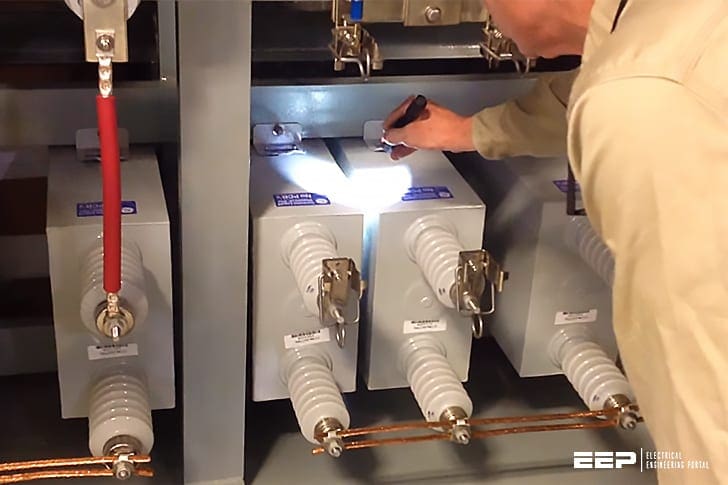
Visual inspection of the capacitor bank must be conducted for blown capacitor fuses, capacitor unit leaks, bulged cases, discolored cases, and ruptured cases.
An infrared camera is very useful for inspecting the substation equipment for overheated joints and surfaces, and records can be maintained for future reference. Pole-mounted capacitor units should be examined for exterior corrosion.
8. Physical Inspection and Measurements
Physical inspection and measurements should include loose connections, overheated lead wires, and faulty fuse tubes.
Fuses should be inspected for evidence of overheating or other such damage. The protection devices should be inspected for proper settings including the position of the current transformer and the potential transformer.
The capacitance of the bank should be measured and compared with the previous measurements.
References:
- Power System Capacitors by Ramasamy Natarajan
- Substation design / Application guide – V AYADURAI BSC, C.Eng, FIEE Engineering Expert


Inspection procedures and checklist parameters are well specified. Good article
mice sir very great full
Good
Dear sir
how can i test the capaitance of each cell.
which the device can i use it to do that.
and if there any sheet can explain the real reading with the acceptable and not acceptable reading
thanks
Ali from Iraq
Hi, I am an Instructional Designer with Pepco Holdings Incorporated, an Exelon Utilities Company. I am asking you if I can embed some of your content here from your Inspection- capacitor banks into portions of my course. Your source content is: https://electrical-engineering-portal.com/inspection-capacitor-banks,
Best regards,
Robert Jasinski
Instructional Designer
302-690-5809
New Castle Regional Office
Newark, DE 19702
[email protected]
Kindly want learn more about power factor bank
will you please upload detailed calculations for selecting HT breakers,HT motors ,depending on fault and torque point of view respectively…..
cool way of learning and transfer of knowledge
Good