
Estimated Study Time: 16 minutes
Manual transfer switch installation
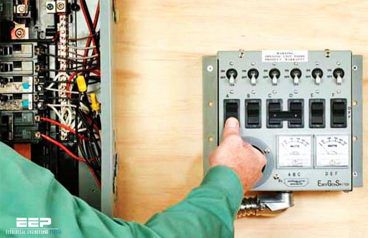
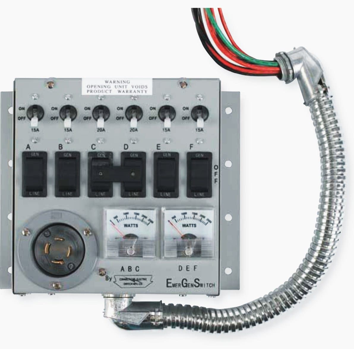
A manual transfer switch is installed next to the main service panel to override the normal electrical service with power from a backup generator during a power outage. Manual transfer switches require an operator to change the power source, while automatic switches detect the loss of power, start the backup generator, and switch over to the backup power feed.
 How to install a manual transfer switch for backup system in 16 steps
Because the amount of electricity created by a backup generator is not adequate to power all of the electrical circuits in your house, you’ll need to designate a few selected circuits to get backup current.
But, select backup circuits first :)
Before you purchase a backup generator, determine which loads you will want to power from your generator in the event of a power loss. Generally you will want to power your refrigerator, freezer, and maybe a few lights. Add up the running wattage ratings of the appliances you will power up to determine how large your backup generator needs to be.
Because the startup wattage of many appliances is higher than the running wattage, avoid starting all circuits at the same time—it can cause an overload situation with your generator.
Here are some approximate running wattage guidelines (use this MS Excel Spreadsheet for calculating electrical loads):
- Refrigerator: 750 watts
- Forced air furnace: 1,100 to 1,500 watts
- Incandescent lights: 60 watts per bulb (CFA and LED lights use less wattage)
- Sump pump: 800 to 1,000 watts
- Garage door opener: 550 to 1,100 watts
- Television: 300 watts
Add the wattage values of all the loads you want to power, and multiply the sum by 1.25. This will give you the minimum wattage your generator must produce. Portable standby generators typically output 5,000 to 7,500 watts.
Most larger, stationary generators can output 10,000 to 20,000 watts (10 to 20 kilowatts).
Let’s describe 14 steps fot installing a manual transfer switch:
Step #1
Turn off the main power breaker in your electrical service panel. CAUTION: The terminals where power enters the main breakers will still be energized.
Step #2
Determine which household circuits are critical for emergency usage during a power outage. Typically this will include the refrigerator, freezer, furnace, and at least one light or small appliance circuit.
Step #3
Match your critical circuits with circuit inlet on your pre- wired transfer switch. Try to balance the load as best you can in the transfer switch: For example, if your refrigerator is on the leftmost switch circuit, connect your freezer to the circuit farthest to the right.
Double-pole (240-volt) circuits will require two 120-volt circuit connections. Also make sure that 15-amp and 20-amp circuits are not mismatched with one another.
Step #4
Select and remove a knockout at the bottom of the main service panel box. Make sure to choose a knockout that is sized to match the connector on the flexible conduit coming from the transfer switch.

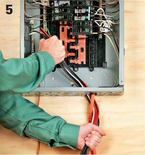
Step #5
Feed the wires from the transfer switch into the knockout hole, taking care not to damage the insulation. You will note that each wire is labeled according to which circuit in the switch box it feeds.
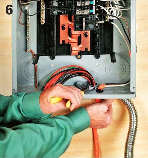
Step #6
Secure the flexible conduit from the switch box to the main service panel using a locknut and a bushing where required.
Step #7
Attach the transfer switch box to the wall so the closer edge is about 18 inches aways from the center of the main service panel. Use whichever connectors make sense for your wall type.

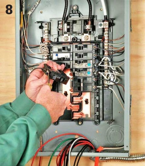
Step #8
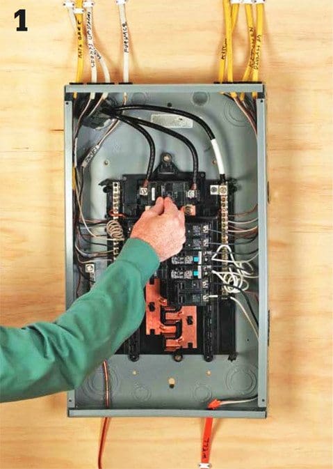
Remove the breaker for the first critical circuit from the main service panel box, and disconnect the hot wire lead from the lug on the breaker.
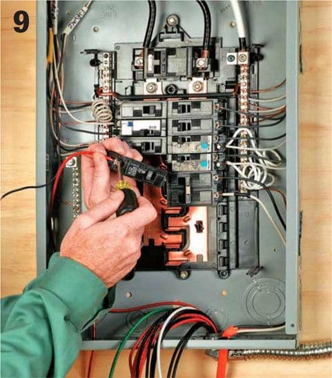
Step #9
Locate the red wire for the switch box circuit that corresponds to the circuit you’ve disconnected. Attach the red wire to the breaker you’ve just removed, and then reinstall the breaker.
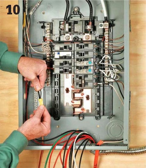
Step #10
Locate the black wire from the same transfer switch circuit, and twist it together with the old feed wire, using a yellow wire connector. Tuck the wires neatly out of the way at the edges of the box.
Proceed to the next circuit, and repeat the process.
Step #11
If any of your critical circuits are 240-volt circuits, attach the red leads from the two transfer switch circuits to the double-pole breaker. The two circuits originating in the transfer switch should be next to one another, and their switches should be connected with a handle tie.
If you have no 240-volt circuits you may remove the preattached handle tie and use the circuits individually.

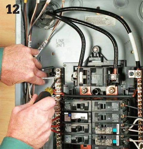
Step #12
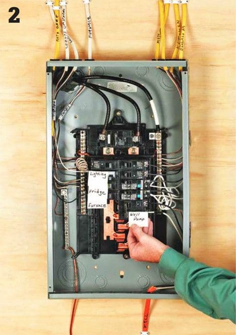
Once you have made all circuit connections, attach the white neutral wire from the transfer switch to an opening in the neutral bus bar of the main service panel.
Step #13
Attach the green ground wire from the transfer switch to an open port on the grounding bar in your main service panel. This should complete the installation of the transfer switch.
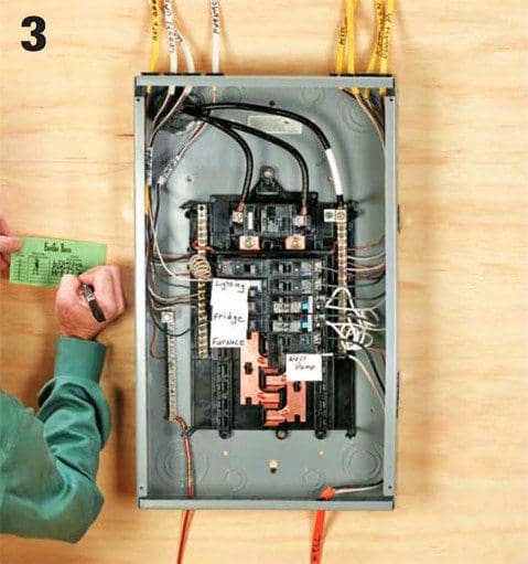
Replace the cover on the service panel box, and make sure to fill in the circuit map on your switch box.

Step #14
Begin testing the transfer switch by making sure all of the switches on it are set to the LINE setting. The power should still be OFF at the main panel breakers.
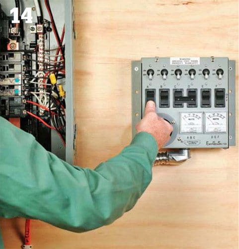
Make sure your standby generator is operating properly and has been installed professionally.

Step #15
Before turning your generator on, attach the power cord from the generator to the switch box. Never attach or detach a generator cord with the generator running. Turn your standby power generator on, and let it run for a minute or two.

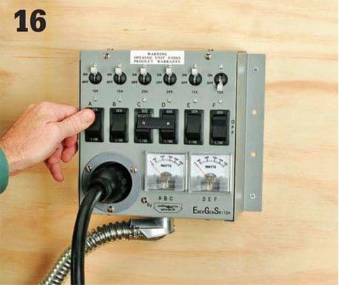
Step #16
Flip each circuit switch on the transfer switch box to GEN one at a time. Try to maintain balance by moving back and forth from circuits on the left and right side. Do not turn all circuits on at the same time. Observe the onboard wattage meters as you engage each circuit, and try to keep the wattage levels in balance.
When you have completed testing the switch, turn the switches back to LINE, and then shut off your generator.
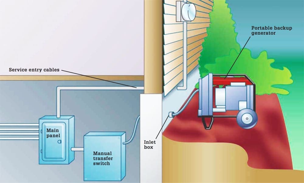
Few Words on Typical Backup System
Backup generators supply power to a manual transfer switch, which disconnects the house from the main service wires and routes power from the generator through selected household circuits.
Installing a backup generator is an invaluable way to prepare your family for emergencies. The simplest backup power system is a portable gas-powered generator and an extension cord or two.
A big benefit of this approach is that you can run a refrigerator and a few worklights during a power outage with a tool that can also be transported to remote job sites or on camping trips when it’s not doing emergency backup duty. This is also the least expensive way to provide some backup power for your home.
You can purchase a generator at most home centers and be up and running in a matter of hours. If you take this approach, it is critically important that you make certain any loads being run by your generator are disconnected from the utility power source.
The next step up is to incorporate a manual transfer switch for your portable generator. Transfer switches are permanently hardwired to your service panel. They are mounted on either the interior or the exterior of your house between the generator and the service panel.
If the inactive utility power line is attached to the service panel, “backfeed” of power from your generator to the utility line can occur when the generator kicks in. This condition could be fatal to line workers who are trying to restore power. The potential for backfeed is the main reason many municipalities insist that only a licensed electrician hook up a transfer switch.
Using a transfer switch not installed by a professional may also void the warranty of the switch and the generator.
Automatic transfer switches turn on the generator and switch off the utility supply when they detect a significant drop in line voltage. They may be installed with portable generators, provided the generator is equipped with an electric starter.
Large standby generators that resemble central air conditioners are the top of the line in backup power supply systems.
Choosing a Generator
Choosing a generator for your home’s needs requires a few calculations. The chart below gives an estimate of the size of generator typically recommended for a house of a certain size. You can get a more accurate number by adding up the power consumption (the watts) of all the circuits or devices to be powered by a generator.
It’s also important to keep in mind that, for most electrical appliances, the amount of power required at the moment you flip the ON switch is greater than the number of watts required to keep the device running.
For instance, though an air conditioner may run on 15,000 watts of power, it will require a surge of 30,000 watts at startup (the power range required to operate an appliance is usually listed somewhere on the device itself). These two numbers are called run watts and surge watts.
Generators are typically sold according to run watts (a 5,000-watt generator can sustain 5,000 watts).
They are also rated for a certain number of surge watts (a 5,000-watt generator may be able to produce a surge of 10,000 watts). If the surge watts aren’t listed, ask, or check the manual. Some generators can’t develop many more surge watts than run watts; others can produce twice as much surge as run wattage.
| Size of house (in square feet) | Recommended generator size (in kilowatts) |
| Up to 2700 | 5 -11 |
| 2071 – 3700 | 14 – 16 |
| 3701 – 4700 | 20 |
| 4701 – 7000 | 42 – 47 |
It’s not necessary to buy a generator large enough to match the surge potential of all your circuits (you won’t be turning everything on simultaneously), but surge watts should factor in your purchasing decision.
If you will be operating the generator at or near capacity, it is also a wise practice to stagger startups for appliances.
Reference: The complete guide to wiring by Black+Decker
Related electrical guides & articles


Edvard Csanyi
Hi, I'm an electrical engineer, programmer and founder of EEP - Electrical Engineering Portal. I worked twelve years at Schneider Electric in the position of technical support for low- and medium-voltage projects and the design of busbar trunking systems.I'm highly specialized in the design of LV/MV switchgear and low-voltage, high-power busbar trunking (<6300A) in substations, commercial buildings and industry facilities. I'm also a professional in AutoCAD programming.
Profile: Edvard Csanyi

The 2022 Ford F-150 Lightning has (1) 240V 30 amp generator port in the bed of the truck.
Could I use the truck as the generator?
The transfer switch box has its own breakers for each circuit. So either the power goes from line to your normal breaker, then through the transfer box directly to your house. Or the power goes from your generator, through the breaker in the transfer switch box, and then back to your house. In both cases you have a breaker for that circuit.
the transfer switch has breakers for each switch
Was thinking about a transfer switch prior to reading this article and am surprised that this is how it works. Seems that doing it this way leaves the circuits without breaker protection. I imagined the circuits intended for backup (in my case I lay 3) would be pulled out and wired to a sub panel. A larger, maybe 30A breaker from the main panel would connect to a 1-0-2 switch in the sub panel, which would then feed the breakers. Neutral and grounding bars would be connected as normal to a sub panel. Thoughts?
bought a house the manual box is already there and i bartered the 7500 generator i have used generator in past ..being i live in south florida..but i have no idea what to do with this, I used the one extension cords runing from generator to my fridge and tv ..coupel other things…now i dont know what they set this up for and if i can change it, i also put a freezer, that is full of meat now..in laundry room, they didnt have one
Your safest bet is to have a knowledgeable electrician install it for you. This seems beyond your diy abilities.
Question: I purchased a 10 switch 10-12k1 from Connecticut General. I never used the box only the twist generator outlet. I recently moved and purchased a new outlet. I have 2 blue wires coming from the meters and cant remember where they were hooked up at. Any ideas.
Sorry, got a little quick there. Didn’t even mention that I have a breaker in the main box that goes to a disconnect next to my generator. Both are 50 Amp. The one in the Main breaker is RED, remains off all the time, of course, along with written instructions on the box that the Main and all breakers in the main MUST be in the off position before starting the generator. I then got to the Generator and plug the Disconnect to it. Once in, I start the generator and move in Disconnect to the ON position. Lastly, I go back to the Main box and throw the RED breaker to the ON position. At this point I select those circuits I want to run. Thanks. Sorry. (I have three different electricians tell me this is fine as I long as I let everyone know how it works).
If anyone gets your procedure wrong they can accidentally apply power to the utility while crews are working on what they expect (and perhaps confirmed before you started your generator) to be dead wires. Accidents happen, and I sure wouldn’t want to injure or kill someone by shocking them so they fall off their ladder. In my area, building codes require a transfer switch, to ensure the utility is disconnected.
Unless my eyeballs are deceiving me, picture #12 shows the Neutral (White) from the Generator being attached to the grounding bar in the home box, not the Neutral (White) main bar on the right.
Now I know that the grounds and whites are intermixed on the panel, but the ‘incoming’ white is clearly on the right. It likely wouldn’t make a difference, but I would feel more comfortable with that large white incoming to a lug in the box, be the one that you are attaching the generator white to.
I don’t use a transfer switch on my backup systems. Never have. I shut the main to the street off, then throw all the breakers off in the Main. Start the generator and pick which breakers in the main I want to run. Tks.
Can you please explain in greater detail the wiring procedure for a back up generator without using a transfer switch?
That is the neutral bar also on the left that the white #12 wire is landing on. Look above the branch circuit breakers and you will see a bar connecting the two. Assuming that this training panel is the first means of disconnect for the main electrical service, then you can bond grounds and neutrals together (not under the same lug though). Here is also where you would use the green screw provided with the panel and bond the neutral to the enclosure also. Never bond grounds and neutrals together in any other panel besides the main panel. Any other panel besides the main panel is a sub-panel, you would bring a ground wire to it from the main panel and have all grounds and neutrals separated.
hi – you forget to say that the generator is connected to the main box through an outlet or directly connected to the main box. This is possible and perfectly safe, but you have to be careful as you never want to generate power to the house without having flipped the main breaker (or you’ll be feeding power to your neighbors and maybe kill a lineman) and you never want to have the generator going while you turn on you main master switch (or generator will fry!)
you are correct that the diagrams shown are inconsistent, and should show the ground or earth is one side of the panel and neutral is the other side. But again they are connected together in the main panel so it really doesn’t matter
thanks
In addition to step #14 being unclear, Step #7 is also missing some words: “Attach the transfer switch box to the wall so the closer panel. Use whichever connectors make sense for your wall type.”
It’s been a year and no editing has taken place so I’m not holding my breath that this will be rectified.
Sorry, I completely missed your first comment at that time. My apologies. However, I updated #7 and #14, so they make sense now. Sorry once again.
Step #14 is not clear, missing some text and the photo is not relevant to the text:
“Begin testing the transfer switch by making sure all of the be OFF at the main panel breakers.”
On the main panel, should all individual breakers be off or only the main?