Installation and commissioning
Purchasing a power transformer for a project is always challenging for every electrical engineer dealing with the procurement. You could omit dozens of possible details from the final specification and get crucified by the company management if you accidentally forget something. And it’s not over, there is more.

After ordering stress, the real challenges are coming – transformer transportation, installation, and commissioning on the site. So, a lot of hard-working hours will pass before you go peacefully to bed.
This technical article describes general experience, recommendations and minimum requirements both from the point of purchaser and transformer manufacturer. However, these may be overruled or supplemented by local regulations and the suppliers or purchasers specific instructions.
I like to say, the heavier the transformer, the more stress you’ll have!
- General recommendations
- Transformer installation
- Transformer commisioning
1. General recommendations
1.1 Responsibilities (who is doing what)
For large power transformers, the installation and commissioning are normally performed by manufacturer. Distribution transformers are normally installed and commissioned by the buyer. In some cases the installation and commissioning is e.g. performed by the customer and supervised by manufacturer.
Responsibilities are defined in the purchase contract with reference to General conditions, e.g. ORGALIME. Limitation of responsibilities should be defined, e.g. when recommended protection is not installed.
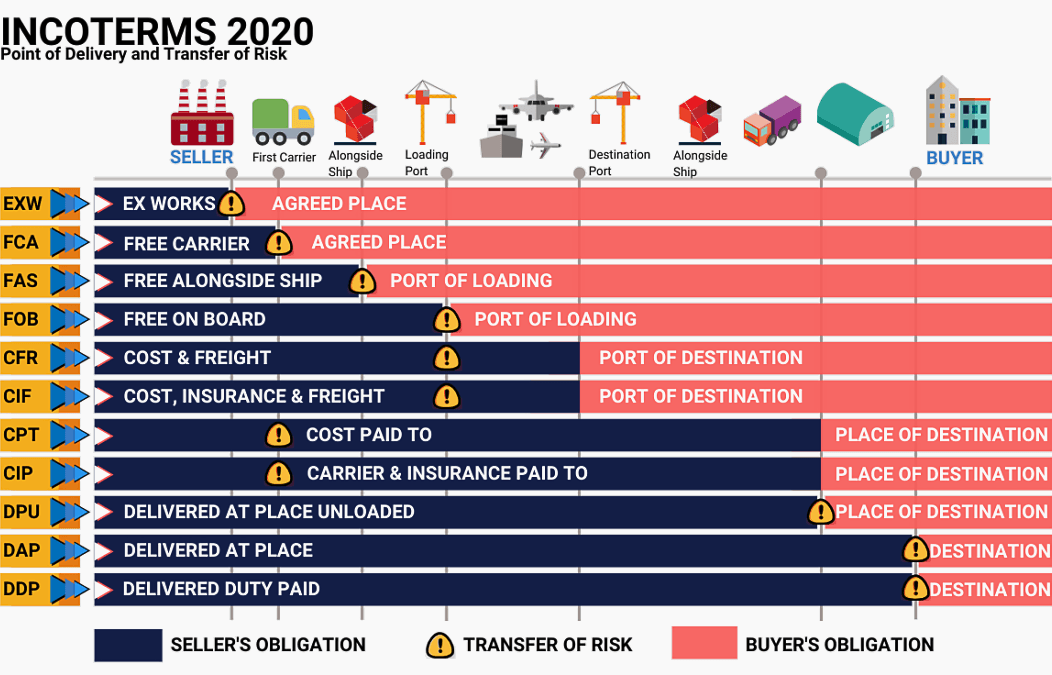
1.2. Incoterms (Transfer of responsibility)
Incoterms defined by International Chamber of Commerce (ICC) make international trade easier and help traders in different countries to understand one another. Incoterms are standard definitions of trade terms and are internationally recognized as indispensable evidence of the buyer’s and seller’s responsibilities under a sales contract.
Incoterms will not apply unless specifically incorporated into the contract.
Those standard trade definitions that are most commonly used in international contracts can be viewed in the wall chart below.


2. Transformer installation
2.1 Power- and large distribution transformers
Installation and commissioning should preferably be performed by the supplier or in close cooperation with the supplier. The contract describes what to be performed by the parties.
After the Factory Acceptance Test (FAT), the transformer is disassembled and made ready for shipping. Depending on the size and voltage class of the transformer more or less of the equipment on the transformer is dismantled prior to transport.
During transport the transformer is filled with dry air with a certain overpressure in order to avoid moisture absorption in the insulation. Before leaving the factory a tightness test is performed. Smaller transformers like large distribution transformer might be shipped with oil.
The weight limit for when the transformer is transported with or without oil depends on several factors like the transport facilities (trucks, boat, cranes), weight limits on roads, bridges etc.
Special transport for 20+ ton transformer
For transformers with a transport weight above 20 ton, which usually is the case for power- and large distribution transformers, special transport is required. This means, transport is performed by experts in handling heavy goods. During transport, the transformer should be equipped with an impact recorder. This is to record if anything should happen to the transformer during transport and during handling at site.
Some recorders register impacts (G-forces in x, y and z-direction) and exactly when the impacts occur. This is essential in the event the transformer has been exposed to abnormal impacts and to determine which party has the transport responsibility at the time of the impact.
The recorder must not be dismantled and the recording finally read before the transformer is at its final destination. If specified, this must be performed in the presence of the parties responsible for the various sections of the transport.
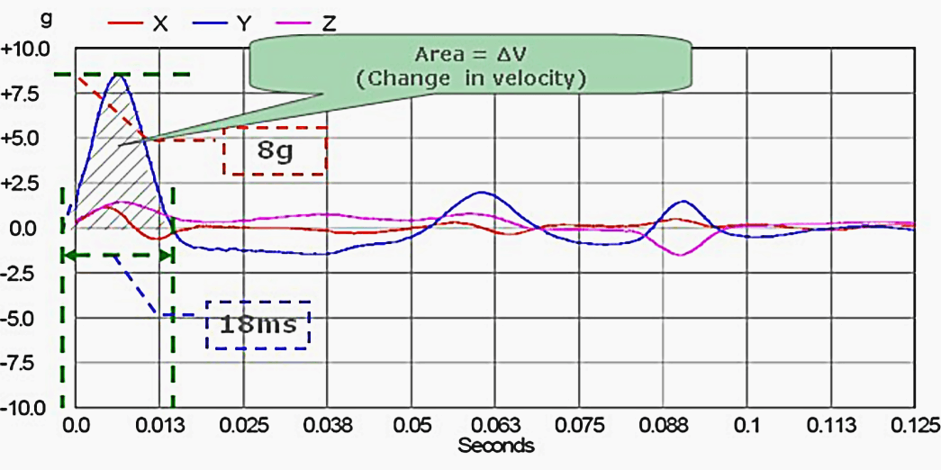
As it can be seen in the graph above:
- Amplitude (a) = 8g
- Duration (t) = 18ms or .018s
- Frequency (1/2t) = 1/ (2 * 0.018) = 28 Hz
- Shock of: [email protected] or [email protected]
The transformer should be insured during the transportation either by the supplier or the purchaser, depending on the terms of delivery. Terms of delivery am included in the contract between the supplier and the purchaser. E.g., if the terms are EXW, the purchaser takes over the responsibility (risk) for the transformer when it is leaving the suppliers premises.
If this is the condition, it is up to the purchaser whether or not the transformer should be equipped with an impact recorder.
When manufacturer supplies new power- and large distribution transformers, the preferred terms of delivery normally are DDP or DDU. In this case the supplier is responsible for the transformer until the arrival at the agreed destination. The transformer should then be equipped with impact recorder.
If the purchaser unloads a transformer with possible transport damage without consulting the supplier, the purchaser has the full responsibility. If it is specified that all handling, lifting, installation, oil filling and oil processing must be carried out by the supplier or under supervision of a representative from the supplier the warranty is only valid when this requirement is fulfilled.


The impact recorder must not be removed until the transformer is placed and fixed on its final site foundation. If storage of the transformer is required prior to energizing this must be performed according to the supplier’s instructions and the conditions for extended warranty must be agreed between the parties.
2.2. Distribution transformers
2.2.1. Transport
The transformer is supplied filled with liquid and normally all accessories fitted, except for the largest units. The radiators may be dismantled during transport.
During transport the following should be considered:
- Angle of tilting exceeding 10° must be specified in the contract,
- Prevention of damage to bushings, corrugated panels or radiators and accessories,
- Larger transformers should preferably be positioned with the longitudinal axis in the direction of movement,
- Secure against movement by means of e.g. wooden blocks and lashes,
- Adapt vehicle speed to the road conditions,
- Vehicle capacity must be adequate for the transport weight of the transformer,
- Any impact recorders to be specified in the contract,
- Any use of crates or containers.
2.2.2. Transformer handling and lifting
Only approved and suitable lifting equipment must be used. Use a forklift only on transport pallets or transformer bottom. Do not apply load to corrugated fins or radiators and their supports. Use the provided lifting lugs only. When lifting a transformer with cable boxes on the cover, special cam must be taken.
When hydraulic jacks are used, only provided jacking points must be used, and in such a way that twisting forces on the transformer tank am avoided.


2.2.3. Receiving the transformer at site
Manufactured transformers must be thoroughly tested and inspected prior to shipping, but upon receiving the transformer at site, it should be inspected carefully.
To be inspected:
- The way in which the transformer has been secured on the trailer,
- That the delivery is complete according to order confirmation,
- Compare the packing list with the goods received,
- The transformer nameplate,
- Liquid level, when applicable. Any leakages?
- External damage, e.g. cracks in bushings,
- Impact recorders indications when applicable.
The receipt of the unit must be signed for and the result of the inspection must be noted. Transformer shipments are normally insured. In case of damage revealed during the receiving inspection do any of the following:
- Make necessary arrangement to avoid further damage,
- Contact the insurance company concerned and the manufacturer,
- Make a report of the damage immediately,
- No repairs should be started until responsibilities am clarified and actions are agreed upon all involved parties.
2.2.4. Transformer storage prior to energizing
When storage of the transformer is required, the following recommendations should be noted:
- Preferably in dry and clean locations, without any possibilities of mechanical damage and on a solid foundation,
- If the transformer does not have a structural steel base, it should be placed upon supports to allow ventilation under the bottom of the transformer base,
- The liquid conservator and dehydrating breather must be checked to ensure that dry air is breathed. (Conservator type only). Liquid samples must be analyzed regarding moisture content prior to energizing,
- Humidity/condensation in control cubicles, driving mechanism for on-load tap changer, cable boxes, dry-type transformers etc. should be inspected/removed,
- Minimum storage temperature for dry-type transformer can vary from —25°C to —60°C, depending on the manufacturer.
- Prior to energizing, perform a insulation resistance test between the different windings, and from the windings to earth. This applies to dry-type in particular.


2.2.5. Transformer erection at site
In determining the location of a transformer, give careful consideration to accessibility, safety, ventilation and ease of inspection. Make sure the foundation for mounting the transformer is entirely adequate. Ventilate the erection site properly. As a guide each kilowatt of losses requires 4 cubic meters of air circulation per minute.
Observe local authorities regulations for civil engineering of transformer cells, safety regulations, fire protection regulations. A liquid containment tank may be required. A transformer equipped with wheels must be prevented from moving by chocking the wheels.
2.2.6 Network connection
2.2.6.1 Electrical clearances in air
Maximum system voltage (kV) | 3.6 | 7.2 | 12 | 17.5 | 24 | 36 | 72.5 |
Lightning impulse withstand voltage (kV) | 45 | 60 | 75 | 95 | 125 | 170 | 325 |
Minimum clearance according to IEC 60076-3, phase to phase and phase to earth (mm) | 60 | 90 | 110 | 170 | 210 | 280 | 630 |
Note! – Testing or well documented local practice can allow the use of reduced clearances.
2.2.6.2 Connecting transformer terminals to the networks
Observe local authorities safety regulations and regulations for electrical installations. Conductors, busbars and cables must be installed such that minimal mechanical stress is transferred to the bushings. Conical washers must be used in order to obtain the required contact pressure. Nuts should be adequately locked. Flexible connectors must be used between the terminals and the bars, when connecting to low voltage busbars. Suitable cable lugs must be used when connecting low voltage copper cables.
The aluminium surface must be larger than the copper surface. Aluminium parts must always be placed above copper parts so that water cannot drain from the copper parts onto the aluminium (corrosion).


It must be remembered that good contact between joined aluminium surfaces can be achieved only if the no conducting oxide film is removed with a wire brush, file or similar immediately before joining, and renewed oxidation is prevented by applying a thin protective film of grease (petroleum jelly).
Jointing compound, which prevents the access of air and humidity into joints, must be used in the joint. The zinc crystals of the compound break down the layer of oxide on the aluminium. Minimum electrical clearances must be obtained. Suitably strong steel bolts and nuts must be used for tightening the joint.
The tightening torque values given below are recommended to be used in external transformer joints.
2.2.6.3 Tightening torque
When disk-type spring washers am used, the nuts should only be tightened until the washer becomes flat.
Bolt size | Recommended tightening torque/Nm |
Property class (Bolt 8.8 Nut 8) | |
M5 | 3,0 |
M6 | 5,5 |
M8 | 15,0 |
M10 | 30,0 |
M12 | 60,0 |
M16 | 120,0 |
2.2.7 Earthing
Earth the transformer at the earthing terminals provided. Earthing resistance must be according to electricity utilities- or national standards.
2.2.8 Protective equipment
Connect the equipment, and check the functions:
- Thermometer with contacts for alarm and tripping signals,
- When applicable, oil level indicator with contacts for alarm signal,
- Gas relay with contacts for alarm and tripping signals,
- Pressure relief device with contacts for alarm signal.
- Recommended thermometer settings for ONAN transformers:
Type of temeperature equipment Alarm Tripping Oil thermometer setting 85°C 100°C Oil thermometer setting, when combined with a winding temperature temperature indicator 90°C 105°C Winding temperature indicator setting 105°C 135°C - Recommended thermometer settings for dry-type transformers according to the relevant temperature class:
Temeperature class Alarm Tripping 105 (A) 90°C 105°C 120 (E) 105°C 120°C 130 (B) 115°C 130°C 155 (F) 140°C 155°C 180 (H) 165°C 180°C 200 220
2.2.9 Insulation resistance
Check the insulation resistance between HV and LV as well as windings to earth. Minimum value is 1000 ohm per volt service voltage.
2.2.10 Off-circuit/on-load tap changer
The following checks must be performed:
- Check the galvanic contact between the winding and the tap-changer in all positions,
- Compare the voltage ratio of the transformer and the network voltages, and select the suitable tap changer position.
2.2.11 Mechanical checks
The following mechanical checks must be performed:
- Check the liquid level,
- Tighten all leaking gaskets carefully,
- After completed installation work, surface damage caused by transportation and installation work must be repaired,
- Condition of dehydrating breather. (For conservator type only),
- Finally the transformer must be cleaned.


3. Transformer commisioning
3.1. Energizing of transformer
Prior to energising, the transformer has to be checked. If applicable the following items should be reviewed:
Item No.1 – Inspection of transformer
Item No.2 – Check impact recorder: If impacts above a certain level are recorded the transformer must be checked for transport damage,
Item No.3 – Check, painting, leakages and fastening: Conservator, cover, tank and coolers
Item No.4 – Bleeding: Cover, bushings, tap changer, Buchholz relay, cooling equipment
Item No.5 – Earthing of: Transformer, cabinets, current transformers, surge arresters, RC-network, tap-changers, oil filter etc.
Item No.6 – Cooling equipment:
- OFWF: Check the mounting direction of oil pumps, oil flow-, and water flow indicators. Adjust water- and oil flow indicators. Check the rotation direction of the motors, motor voltage, motor protection. Check that all valves are open.
- OFAF: Check the mounting direction of oil pumps, oil flow indicators. Adjust oil flow indicators. Check the rotation direction of the motors, motor voltage, motor protection. Check that valves are open.
- ONAF: Check the rotation direction of the motors, motor voltage, motor protection. Check that valves am open.
- ONAN: Check that valves are open.
Item No.7 – Tap-changer, oil filter and motor drive unit: Should be checked according to guidelines given by the manufacturer for this equipment, e.g. locking of shaft connections, mounting direction protective relay, symmetrical coupling, motor voltage, phase rotation, motor protection, end limit switches (electrical and mechanical), emergency stop — raise and lower switch, step by step, remote controlling etc.
The checklist may vary depending on selected manufacturer, type of tap-changer and equipment installed.
Item No.8 – Current transformers: Check polarity, and that all secondary CT circuits am closed before energising the transformer. If a current transformer is not in use it has to be short cirquited and earthed.
An open circuited current transformer gives hazardous voltages and is dangerous to personnel and equipment. It can result in personal injury, death or property damage.
Item No.9 – Protective equipment:
- Check that all alarm signals from protective equipment is functioning, such as thermometers, oil level indicators, Buchholz relay, oil flow-, water flow indicators etc.
- Check that all trip signals from protective equipment is functioning, such as thermometers, oil level indicators, Buchholz relay, tap-changer protective relay, etc. Trip signals are hard wired to the circuit breaker and all trip signals should be checked to verity that the circuit breaker opens when a trip signal is activated.
Item No.10 – Oil sample: o Oil sample must be collected and analysed to check that the oil condition (dielectric withstand voltage and moisture level) fulfils the requirements of IEC or ANSI/IEEE standards.
Item No.11 – Electrical tests: Electrical tests recommended by the supplier should be performed.
After the transformer has been found to be in good condition and the protective equipment is found in order according to the above list, the transformer is ready to be connected to the network (energized).
Modem over-current and differential relays contain a filter which makes the relays insensitive to inrush currents. Older relays may trip the circuit breaker immediately.
See also this technical article about inrush currents:
When does exciting current inrush occur in power transformer?
After the transformer has been connected to the network, gas may be present which cause the gas relay to trip to give an alarm. It could be a false alarm caused by an air bubble, trapped under the cover, and then moved into the gas relay. Air is colourless and odourless. If not air, a gas and an oil sample should be taken for analysis.
Date for formal take-over can vary, but must be clearly stated in the contract between supplier and purchaser. This can be after the transformer is energized or after a test period of the transformer.
A hand-over protocol should be established, signed by both parties.
3.2. Documentation
The following documentation will be handed over to the purchaser at time of take-over as applicable:
- Transformer specification
- Outline drawing
- Transport drawing
- Schematic drawing
- Wiring diagram
- Assembly, operation and maintenance manual
- Technical documentation from sub suppliers (bushings, tap-changer, coolers etc)
- Data sheet transformer oil
- Test protocol (FAT)
- Transport (shipping) documentation
- Trouble shooting guide
- Commissioning report.
- Take-over protocol
Recommended reading:
The wiring diagram and physical layout of the equipment inside the motor control centre
Sources:
- Transformer book by ABB
- Transformer shipping handbook by Sensebig
Many thanks , i follow your articles , it is very important
Highly informative writeup. Thanks
Thank you Foluso.
Thanks you for subject
I am interested in power transformer design.
Its great one. very useful
can u add up some videos on the different transformer testing method in practical. it will be so helpful
Thank you Vimal. Try searching EEP for transformer testing, there are several already published articles and guides with videos you mentioned.