
Estimated Study Time: 23 minutes
Metal-enclosed switchgear
What does it mean ‘metal-enclosed switchgear’? Metal-enclosed switchgear and controlgear are generally assembled from type-tested panels. As per IEC 62271-200 metal-enclosed switchgear installations must be designed so that their insulation capacity, degree of protection, current carrying capacity, switching capacity and mechanical function conform to the requirements set by the testing provisions.
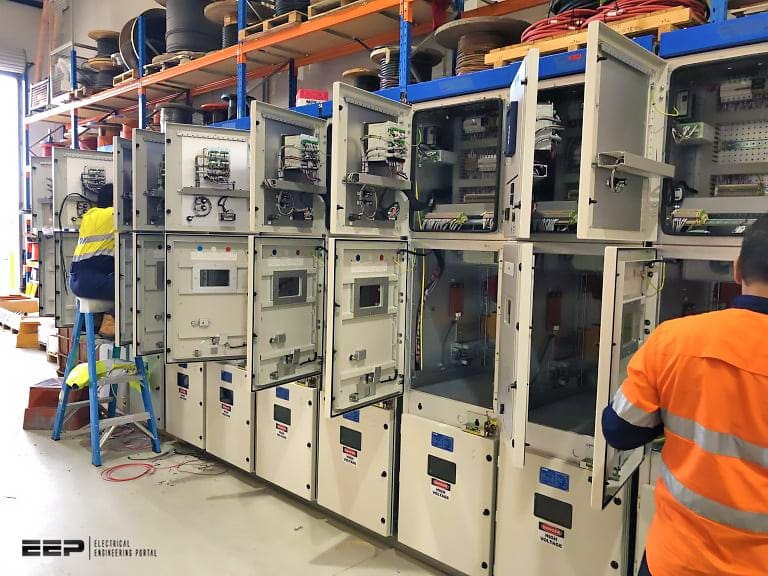
 Installation guidelines for metal-enclosed switchgear and controlgear (IEC 62271-200)
This is verified by a type test on a prototype panel. In addition, a routine test is made on every completed panel or every transport unit. Note that together with standard IEC 62271-200, IEC 62271-1 is always to be observed.
Type-tested switchgear installations with insulated enclosures are subject to IEC 62271-201.
- Rated voltage
- Insulating media
- Degree of protection
- Compartments, accessibility and service continuity
- IAC (Internal Arc Classified) switchgear
1. Rated voltage
The rated values for the insulation level of a switchgear installation must be selected on the basis of the requirements of the system at the installation site from the selection tables in IEC 62271-1. Table 1 shows the selection values for the range of rated voltages up to 52 kV.
The voltage values “over the isolating distance” only apply for switching devices with which the safety requirements for the open contacts of disconnecters must be met.
Table 1 lists two value pairs that can be selected for the rated lightning impulse voltage level for almost all rated voltages.
Table 1 – Rated voltages and insulation levels in the medium voltage range
| Rated voltage Ur/kV (r.m.s. value) | Rated short-duration power-frequency withstand voltage Ud / kV (r.m.s. value) | Rated lightning impulse withstand voltage Up / kV (peak value) | ||
| Line-earth, line-line, across contact gap | Across isolating distance | Line-earth, line-line, across contact gap | Across isolating distance | |
| (1) | (2) | (3) | (4) | (5) |
| 3.6 | 10 | 12 | 20, 40 | 23, 46 |
| 7.2 | 20 | 23 | 40, 60 | 46, 70 |
| 12 | 28 | 32 | 60, 75 | 70, 85 |
| 17.5 | 38 | 45 | 75, 95 | 85, 110 |
| 24 | 50 | 60 | 95, 125 | 110, 145 |
| 36 | 70 | 80 | 145, 170 | 160, 195 |
| 52 | 95 | 110 | 250 | 290 |
When making the selection, the degree of danger from lightning and switching overvoltages, the type of neutral treatment and, if applicable, the type of overvoltage protection should be considered. The higher value pairs in each case are the ones to be selected for installations and equipment exposed to atmospheric overvoltages, e.g. by direct connection to overhead lines.
The lower value pairs can be used for installations that are not exposed to atmospheric overvoltages or are protected from these overvoltages by arresters.
2. Insulating media
IEC 62271-200 covers both switchgear in which atmospheric air acts as the gaseous insulation within the enclosures and also switchgear in which an insulating medium in the form of a fluid other than the atmospheric air (e.g. SF6) is used.
So, we have an air-insulated switchgear (AIS) and gas-insulated switchgear (GIS).
Interesting reading:
What would be the best solution for urban supply networks – AIS or GIS system?
3. Degree of protection
The metallic and earthed enclosure protects personnel against approach to live components and against contact with moving parts. It also protects the installation against the penetration of foreign bodies. One of three different degrees of protection may be selected for switchgear to IEC 62271-200.
The difference is whether the enclosure is suitable for repelling fingers or similar objects (IP 2X to IEC 62271-1, Minimum requirements for metal-enclosed switchgear), rigid wires more than 2.5 mm in diameter (IP 3X) or rigid wires more than 1 mm in diameter (IP 42).
4. Compartments, accessibility and service continuity
Within the general term “metal-enclosed”, distinctions were formerly made between three categories – “metal-clad”, “compartmented” and “cubicle” switchgear – depending on the design of the internal compartmentalization. This structural definition of compartmentalization has now been replaced in IEC 62271-200 by classification according to the accessibility of the compartment with high voltage components.
With a view to the accessibility of the compartments, the following distinctions are made:
- Interlock-controlled accessible compartment: Integral interlocks enable access to open the compartment for normal operation and/or maintenance.
- Procedure-based accessible compartment: Access to open the compartment for normal operation and/or maintenance is regulated by a suitable procedure combined with locking.
- Tool-based accessible compartment: The compartment can be opened with tools, but not for normal operation and/or maintenance.
- Non-accessible compartment
Categorization is then determined by the loss of service continuity, focusing on the main switching device. The LSC categories result from the scope of switchgear components to be taken out of service when a compartment is opened:
4.1 LSC1 category functional unit
This category covers the lowest level of service continuity. It applies to an accessible compartment in a panel which would require at least one further panel to be taken out of service when it is opened. If a busbar compartment is opened, all the panels in the relevant section must be de-energized.
4.2 LSC2 category functional unit
This form is intended to allow maximum continuity of service of the network during access to the high voltage compartments inside the switchgear and controlgear. This means that the accessible high voltage compartments in a functional unit can be opened while the other functional units in the same section remain energized.
Category LSC2 requires that at least the connection compartment may be opened while keeping the busbar(s) energized.

4.3 LSC2A category functional unit
Category 2A stands for a panel which has to be taken completely out of service when a compartment is opened. The panel has partition walls separating it from the adjacent panels and at has least two compartments and an isolating distance.

4.4 LSC2B category functional unit
Category 2B provides the least restriction to service continuity and means that all other panels in the installation and all cable termination compartments (including that in the panel concerned) remain in operation when a compartment is opened.
When a compartment has been opened, partitions and shutters to the adjacent compartment or panel provide a degree of protection against live high voltage components. The “partition class” indicates whether the partition is metallic throughout or contains parts of insulating material.
4.5 Examples of applied categories
The next figures illustrate three functional units in ABB’s UniSec medium voltage switchgear, all with high categories (LSC2, LSC2A and LSC2B).
These categories are able to ensure maximum continuity of service but with the degree of accessibility required for maintenance and servicing work:
- SBC (circuit-breaker with switch-disconnector),
- SFC (switch-disconnector with fuses),
- WBC (unit with withdrawable circuit breaker) and
- HBC (unit with vacuum circuit breaker and gas insulated disconnector)

4.6 Class PM
“Partition of metal”: Metallic shutters and partitions between live parts and an open compartment. Class PM is the best choice for the safety of personnel working in the compartment, since it ensures that the structure is homogeneously earthed.
Figure 7 illustrates metallic shutters, closed when the circuit-breaker is withdrawn and connected to the structure of the circuit-breaker compartment.

4.7 Class PI
“Partition of insulating material”: Discontinuity in the metallic partition/shutter between live parts and an open compartment, which is covered by insulating material.
Both partition classes provide the same protection against accidental contact for the worker, but a metallic partition also screens off the electric field.
5. IAC (Internal Arc Classified) switchgear
All specialists are in basic agreement that manufacturers and users must make every effort to prevent under all circumstances faults in switchgear installations in which internal arcing occurs. However, it is also acknowledged that such faults cannot be completely prevented in all cases.
For this reason, it is expected that current switchgear designs have been tested for response to internal arcing.
Immediately after the arc has been ignited, the gas in the immediate vicinity of the am heats up instantly, causing a very steep rise in pressure in the compartment concerned. This pressure increase would continue to the load limit of the enclosure if pressure relief vents were not built into it.
The sealing covers or membranes of these vents respond in ca. 5 to 15 ms and open the path to allow the heated gases to vent (Figure 9). This characteristic process is not determined only by the response time of the pressure relief valves but it also results from the mechanical inertia of the heated gas mass.
A powerful ejection of still heated gases of low density and glowing particles occurs in the subsequent emission phase and in the thermal phase.

Where,
- Compression phase (pressure build-up),
- Expansion phase (pressure relief),
- Emission phase (hot gases released),
- Thermal phase (ejection of glowing particles)
a) isochorous pressure rise,
b) opening of pressure relief valves.
Guidelines for testing metal-enclosed switchgear for its response to internal arcing can be found in IEC 62271-200.
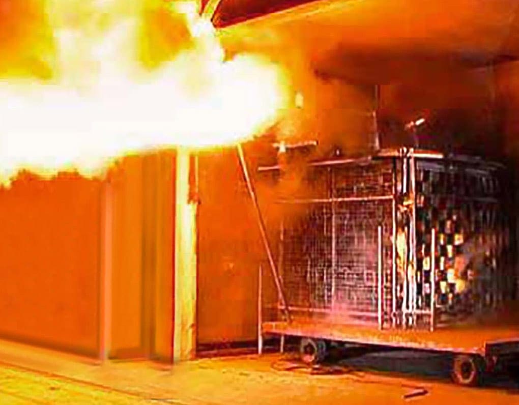
The specified test conditions require the internal arcing to be ignited with a thin ignition wire in each compartment of the panel to be tested. The point of ignition and the direction of energy flow are specified in such a way that the arc bums as long as possible at the most distant location from the feeder. The short-circuit test plant supplying the test object, which consists of at least two panels, must have sufficient power to allow a short-circuit current as high as the rated short-time withstand current to flow in three phases over the internal arcing during the agreed duration of the test (recommended times 1.0, 0.5 or 0.1 s).
This will cover the normal protection grading times at full short-circuit current. With this short-circuit duration, the test result is restricted to the question of whether the tested compartment withstands the stress caused by the internal overpressure.
During the test, fabric indicators (black, cretonne or cotton-wool batiste) are stretched vertically at a defined spacing on metal frames in front of the accessible walls of the panels and horizontally at 2 m height above the zone where personnel would be when operating the installation.
5.1 IAC classification
The classification must be indicated in the following way:
- Classification: IAC (Internal Arc Classified)
- Type of accessibility: A, B, C
- Classified sides of the enclosures: F, L, R
- Rated values of three-phase arc fault: current [kA] and arcing time [s]
- Rated values of single-phase arc fault (when applicable): current [kA] and arcing time [s]
With metal-enclosed switchgear, a distinction is made between three degrees of accessibility which are possible at the point of installation:
- Accessibility type A: For authorized personnel only
- Accessibility type B: Unlimited access for the general public
- Accessibility type C: accessibility restricted by installation out of reach and beyond the zone accessibile to the public
The front side must be clearly indicated by the manufacturer. Classified sides do not apply to switchgear with accessibility type C.
On completion of the short-circuit test, the behaviour of the tested panels is recorded on the basis of five criteria:
- Criterion 1: Doors and covers remain closed. Deformations are acceptable if no part reaches the indicators or walls.
- Criterion 2: No fragmentation of the enclosure occurs within the duration of the test. Projections of small parts, up to an individual mass of 60 g, are acceptable.
- Criterion 3: Arcing does not cause holes in the accessible outer sides of the enclosure up to a height of 2 m
- Criterion 4: Horizontal and vertical indicators must not be ignited by hot gases. Permitted exceptions: ignition by burning paint coatings, stickers or glowing particles.
- Criterion 5: Earth connections remain effective, as demonstrated by visual inspection.
5.2 Few IAC examples:
IAC AFL 12.5 kA 1s switchgear
The switchgear is protected on three sides (front and lateral) for 12.5 kA arc fault current and 1 s arc fault duration. It is available in two versions:
Version 1 – Switchgear installed against the wall. In this case, the rear part of the switchgear and the wall form a duct through which gas can pass.
Version 2 – Switchgear not completely against the wall. In this case, filters installed in the rear part of the unit cool and lower the pressure of the gas before it is released into the environment.
It is clearly forbidden to access the rear part of the switchgear when in service since it is not protected.

IAC AFLR 25 kA 1s switchgear
The switchgear is protected on four sides (front, lateral and rear) for 25 kA arc fault current and 1 s arc fault duration. Filters installed in each unit cool and lower the pressure of the gas before it is released into the environment.

Additional information about internal arc can be obtained in the form of high-speed camera pictures or videos taken during the test, and these are therefore highly recommended.
If the arc fault test is passed, for instance in the context of a type test, this is documented by the designation IAC (“Internal Am Classified”) on the type plate. The confirmation of testing is supplemented by additional data such as the accessibility type, indications of the accessible sides, the test current and duration.
There are further points to be considered over and above criterion 5 of the assessment, as in the event of ejection of hot gases, the switchgear and controlgear itself is not primarily relevant for the effects.
A panel type may be considered fully tested only after this case has been considered.
Countermeasures for protection of the operating personnel against these effects can be as simple as installing screens or discharge plates. At high short-circuit currents, hot gas conduits with blow-out facilities using absorbers discharging into the switchgear installation room are the perfect solution.
However, even better results without additional installations can be achieved if it is possible to limit the arc duration to approximately 100 ms by appropriate trip times. Because the grading times of the system protection do not generally allow such a short-term tripping of the feeder circuit-breaker, additional sensors are required, such as the Ith-limiter.
When one of the pressure relief valves opens and there is simultaneous persistent short-circuit current, it initiates an undelayed trip command to the feeder circuit-breaker. This quenches the internal arc in less then 100 ms. The pressure load on walls, ceilings, doors and windows of the switchgear installation room is the result of the gas ejection during the expansion phase (Figure 9).
The withstand capability can generally not be verified by testing.
All major manufacturers provide calculation programs for determining the pressure development in the switchgear installation compartment to find out whether pressure relief vents are required for the installation room.
Source: ABB
Related electrical guides & articles


Edvard Csanyi
Hi, I'm an electrical engineer, programmer and founder of EEP - Electrical Engineering Portal. I worked twelve years at Schneider Electric in the position of technical support for low- and medium-voltage projects and the design of busbar trunking systems.I'm highly specialized in the design of LV/MV switchgear and low-voltage, high-power busbar trunking (<6300A) in substations, commercial buildings and industry facilities. I'm also a professional in AutoCAD programming.
Profile: Edvard Csanyi

Thanks for all this essential information.
Since the release of IEC 62271-200 (I do not have immediate access to the full document hence my question below) there is developing a school of thought that ALL (previously uninsulated) MV/HV busbars within LSC2B metal enclosed switchgear NOW need to be insulated in order to comply. Is this true or misguided?
Do you explain more about across isolating distance
Thank you for useful information.
Thanks for sharing this wonderful information. This means a lot to me.
Excellent article with practical value.