A. Aerial mounting
A1. Unit capacities, mountings, and types
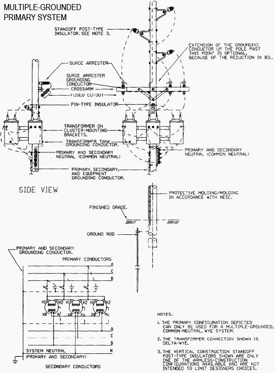
Aerial transformer installations may utilize a three-phase unit or banked single-phase units. Transformers, either singly or in banks, having an individual unit or combined capacity greater than 300 kVA will not be mounted on single wood poles. Special structural considerations will be given for single-pole installations greater than 100 kVA.
Pole-platform mounting (two-pole structure) will not be used, except where other mounting methods are not satisfactory. Cluster mounting for transformer banks is preferred over crossarm mounting as less visually objectionable. Similarly, the cluster or three-phase bracket mountings will be permitted for mounting of surge arresters and cutouts if acceptable to the Using Agency responsible for the operation and maintenance of trans-former installations.
Figures 8-1 and 8-2 indicate transform bank installations. Self-protected transformers have internal primary fuses that must be replaced by experienced personnel. Therefore, self-protected transformers will not be specified.

A2. Location
Aerially mounted installations may supply several buildings. When that is the case, transformers will be installed at the pole location closest to the building with the greatest load. Secondary wiring should drop directly to the buildings served, if the span does not exceed 125 feet; otherwise, intermediate poles are required.
B. Ground level mounting
B1. Types and capacities
Ground-level mounting may be either the pad-mounted compartmental type or the unit substation type. Figure 8-3 shows a typical pad-mounted compartmental transformer installation.
The use of conventional-type (pole-mounted) transformers, with connections to separate primary and secondary protective devices, is not permitted since this type of installation is more dangerous, generally more difficult to maintain, requires more space, and there is rarely a significant cost saving since fencing is required.
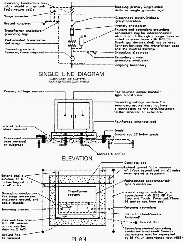
Pad-mounted compartmental transformers may only be used outdoors even when designed for both indoor and outdoor installation. Unit substation transformers may be used indoors or outdoors.
B2. Pad-mounted compartmental liquid-insulated transformers
Three-phase pad-mounted com-partmental transformers may be applied in ANSI standard sizes through 2500 kVA, except that they will not be used where the primary voltage exceeds 15 kV or where fault currents are so large that standard equipment does not provide the required primary interrupting duty.
The choice between pad-mounted, compartmental transform-ers and unit substations in conjunction with integral or non-integral load-center transformers will be based on: the application; potential for expansion; short circuit and protective device coordination; sound engineering judgment; accepted indus-try practice; and the operating, maintenance and reliability considerations listed below:
- If instruments and switches are rou-tinely used by operators, choose unit substations and integral or non-integral load-center transform-ers. For pad-mounted compartmental transformers, instruments and operating devices are inside a locked compartment and are not readily accessible.
. - Pad-mounted compartmental transform-ers require use of a switch stick for switch mecha-nism operation and cable-disconnection (due to the dead-front requirement). The typical high-voltage switch used with unit substations does not require use of a special tool and is therefore easier to operate.
. - Fan cooling and 12 percent additional capacity for 55/65 degree C temperature rise is available for unit substations and integral load-center transformers, but is not available for pad-mounted compartmental transformers which are self-cooled; fans cannot be added to increase the cooling capacity.
B3. Residential service
Pad-mounted trans-formers will be routinely used in residential and light commercial service.
B4. Industrial service
Pad-mounted transform-ers may be used for industrial, commercial, or industrial application, provided that only one building is served; metering and secondary switch-gear can be located in the building; and short circuit and protective device coordination con-straints are met.
B5. Service for large loads
Unit substations and integral and/or non-integral load-center transform-ers will be used for industrial, heavy commercial, and institutional applications involving large loads, multiple building serves, and the require-ments for secondary bus protective devices.
B6. Secondary unit substations
Secondary unit substations with integral or nonintegral outgoing sections will be used. Since neither type is tamper proof, fencing is required. Fence height will be in accordance with the NESC. Transformers larger than 1,500 kVA for 480Y/277 V service and 500 kVA for 280Y/120 V service should be avoided, because of the magnitude of their secondary fault currents.
However, in some cases, it may be more feasible and cost effective to provide 2,000 kVA transformers for 480Y/277 V service and use current-limiting fuses in conjunction with circuit breakers to limit secondary fault currents. The using agency (for Air Force, the Host/REQ CMD) will stipulate demand meter requirements.
B7. Location
Exterior installations are pre-ferred over interior installations because space costs are less; however, secondary feeder lengths may require an interior location or make interior installations economical in some cases.
B7-1 Liquid-filled transformers installed out-doors
Outdoor installations will comply with the NEC, MIL-HDBK-1008A, and the NESC. Trans-formers will be located to preclude any reasonable chance that products of combustion from a trans-former tire will be drawn into the HVAC air intake of adjacent buildings.
The location of pad-mounted transformers will be compatible with the architectural concept and protected from vehicular traffic. Architectural compatibility will be obtained by the proper location in relation to landscaping, the addition of shrubbery around the transformer, or the use of screened fence enclo-sures. The primary service will be underground from pad-mounted transformers. Secondary build-ing connections will use underground cables or bus duct; however, the use of more than six under-ground cables per phase in parallel will not be permitted since complexity of connection can lead to maintenance and space problems.
B7-2 Liquid-filled transformers installed in-doors
Indoor installations will comply with the NEC and MIL-HDBK-1008A. Transformer vaults will be located on the exterior wall of the building, vented to the outside and accessible only from outside the building under normal design conditions.
Air intake fans and louvers of heating, ventilating, and air conditioning (HVAC) systems will be interlocked with the smoke and rate-of-rise detectors in the transformer vault and/or vault rooms. The smoke and rate-of-rise detectors will de-energize the HVAC air intake if a fire occurs in the transformer vault and/or vault rooms. This is not necessary if the HVAC intake is located on the roof or the opposite side of the building from the transformer vault. A sign will be posted on the access doors to a transformer vault which indicates the appropriate fire fighting equipment and proce-dures. Pipes and ducts will not be routed above indoor transformers.
B7-3 Dry-type transformers
Dry-type trans-former applications will comply with the NEC and MIL-HDBK-1008A. Dry-type transformers will be located to preclude any reasonable chance that products of combustion from a transformer fire will be drawn into the building’s HVAC system. Dry-type transformers in ventilated enclosures may be specified for indoor applications in clean, dry environments (not subject to blowing dust, excessive humidity, or corrosive atmosphere) and will be rated for the highest temperature of the location.
Dry type transformers in non-ventilated enclosures may be used for indoor or outdoor applications, if the enclosure is rated for the environment. Hermetically-sealed dry transform-ers (filled with dry nitrogen) will not be specified due to their large size, the inability to add supple-mentary cooling, and problems associated with loss of gas. Transformers protected by cast or impregnanted-epoxy-resin may be used indoors and outdoors, where environmental conditions would shorten the life of a conventional dry transformer.
Specifications will include epoxy encapsulation for the core and for both the high and low voltage windings. Each connection insulation must be compatible with the environment. The specifica-tion for medium-voltage primary transformers will require the basic insulation level to be the same as for liquid-filled transformers in the same voltage class, and will require the transformers to be tested in accordance with applicable ANSI tests for liquid-filled transformers.
C. Underground Mounting
Transformers in un-derground vaults are not permitted except where required to meet airfield clearances.




It’s a good information for me..
Thanks