
Estimated Study Time: 15 minutes
AC converter installation
If the environmental conditions are likely to exceed normal working ranges of an AC converter, then arrangements should be made to provide additional cooling and/or environmental protection.
 Installing AC converter into metal enclosure (photo credit: plctalk.net)
The temperature limits of an AC converter are far more critical than those for an electric motor! Temperature de-rating needs to be strictly applied!
However, it is unlikely that a modern PWM converter will be destroyed if the temperature limits are exceeded. Modern AC converters have built-in thermal protection, usually a silicon junction devices, mounted on the heat sink. The main problem of over-temperature tripping is associated with nuisance tripping and the associated downtime.
Manufacturers provide figures for the losses (watts) when the converter is running at full load.
Adequate provision should be made to dissipate this heat into the external environment and to avoid the temperature inside the converter enclosure rising to unacceptably high levels.
Converters are usually air-cooled, either by convection (small power ratings) or assisted by cooling fans on larger power ratings. Any obstruction to the cooling air flow volume to the intake and from the exhaust vents will reduce efficiency of the cooling.
The cooling air volume flows and the power loss dissipation determine the air conditioning requirements for the equipment room.
The cooling is also dependent on there being a temperature differential between the heat sink and the cooling air. The higher the ambient temperature, the less effective is the cooling. Both the AC converter and motor are rated for operation in an environment where temperature does not exceed 40° C.
In an environment where condensation is likely to occur during the periods when the drive is not in use, anti-condensation heaters can be installed inside the enclosure. The control circuit should be designed to switch the heater on when the drive is de-energised.
The heater maintains a warm dry environment inside the enclosure and avoids moisture being drawn into the enclosure when the converter is switched off and cools down.
AC converters are usually designed for mounting in a vertical position, to assist convectional cooling. On larger VSDs, cooling is assisted by one or more fans mounted at the bottom or top of the heat sink.
Many modern converters allow two alternative mounting arrangements:
1. Surface mounting
Surface mounting, where the back plane of the converter is mounted onto a vertical surface, such as the back of an enclosure. See figures 1 and 2 below.
2. Recessed mounting
Recessed mounting, where the heat sinks on the back of the converter project through the back of the enclosure into a cooling duct. This allows the heat to be more effectively dissipated from the heat sinks. See Figure 3.
Sufficient separation from other equipment is necessary to permit the unrestricted flow of cooling air through the heat sinks and across the electronic control cards.
A general rule of thumb is that a free space of 100 mm should be allowed around all sides of the VSD. When more than one VSD are located in the same enclosure, they should preferably be mounted side by side rather than one above the other.
Care should also be taken to avoid locating temperature sensitive equipment, such as thermal overloads, immediately above the cooling air path of the VSD.
Calculating the dimensions of the enclosure
The enclosure should be large enough to dissipate the heat generated by the converter and any other electrical equipment mounted inside the enclosure. The heat generated inside an enclosure is transferred to the external environment mainly by radiation from the surface of the enclosure.
Consequently, the surface area must be large enough to dissipate the internally generated heat without allowing the internal temperature to exceed rated limits.
The surface area of a suitable enclosure is calculated as follows:

where:
- A – Effective heat conducting area in m2
(Sum of surface areas not in contact with any other surface) - P – Power loss of heat producing equipment in watts
- TMax – Maximum permissible operating temperature of converter in °C
- TAmb – Maximum temperature of the external ambient air in °C
- k – Heat transmission coefficient of enclosure material
Calculation example //
Calculate the minimum size of an IP54 cubicle for a typical PWM type frequency converter rated at 22 kW. The following assumptions are made:
- The converter losses are 600 watts at full rated load.
- The converter is to be mounted within an IP54 cubicle made of 2 mm steel.
- The enclosure is effectively sealed from the outside and heat can only be dissipated from the enclosure by conduction through the steel and by radiation from the external surface into the outside air.
- The cubicle stands on the floor with its back against the wall in an air conditioned room with a maximum ambient temperature 25° C.
- The converter can operate in a maximum temperature of 50° C.
- The heat transmission coefficient is 5.5 (typical for painted 2 mm steel).
The first step is to calculate the minimum required surface area of the enclosure. This can be done by applying the formula for surface area.
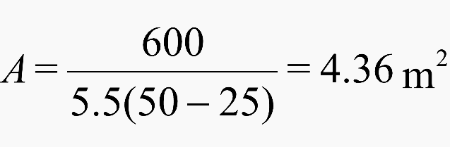
If the cubicle is standing on the floor against a wall, this area applies only to the top, front and two sides of the enclosure. A suitable cubicle can be chosen from a range of standard cubicles or could be fabricated for this installation.
In either case, it is important to take into account the dimensions of the converter and to ensure that there is at least 100 mm space on all sides of the converter.
For a cubicle with dimensions H × W × D standing on the floor against the wall, the effective heat conducting area is:
A = HW + 2HD + WD
Assuming that a standard cubicle is chosen with a height of 2.0 m and a depth of 0.5 m, the width is derived from:
A = 2.0 W + 2 + 0.5 W
A = 2.5 W + 2
Using the required heat dissipation area from the above calculation:
4.36 = 2.5 W + 2 or
2.5 W = 2.36 where
W = 0.94
Clearances around converter
Clearances around the sides of the converter should be checked. With typical converter dimensions of H × W × D = 700 × 350 × 300, the cubicle chosen would provide more than 100 mm of clearance around all the converter and also leave sufficient space for cabling and other components.
From this calculation, it is clear that the overall dimensions of the cubicle can be reduced by the following changes:
- Standing the cubicle away from the wall, at least 200 mm
- Reducing the ambient temperature, turning down the air-conditioning
- Providing ventilation to the cubicle to improve heat transfer

Ventilation of enclosures
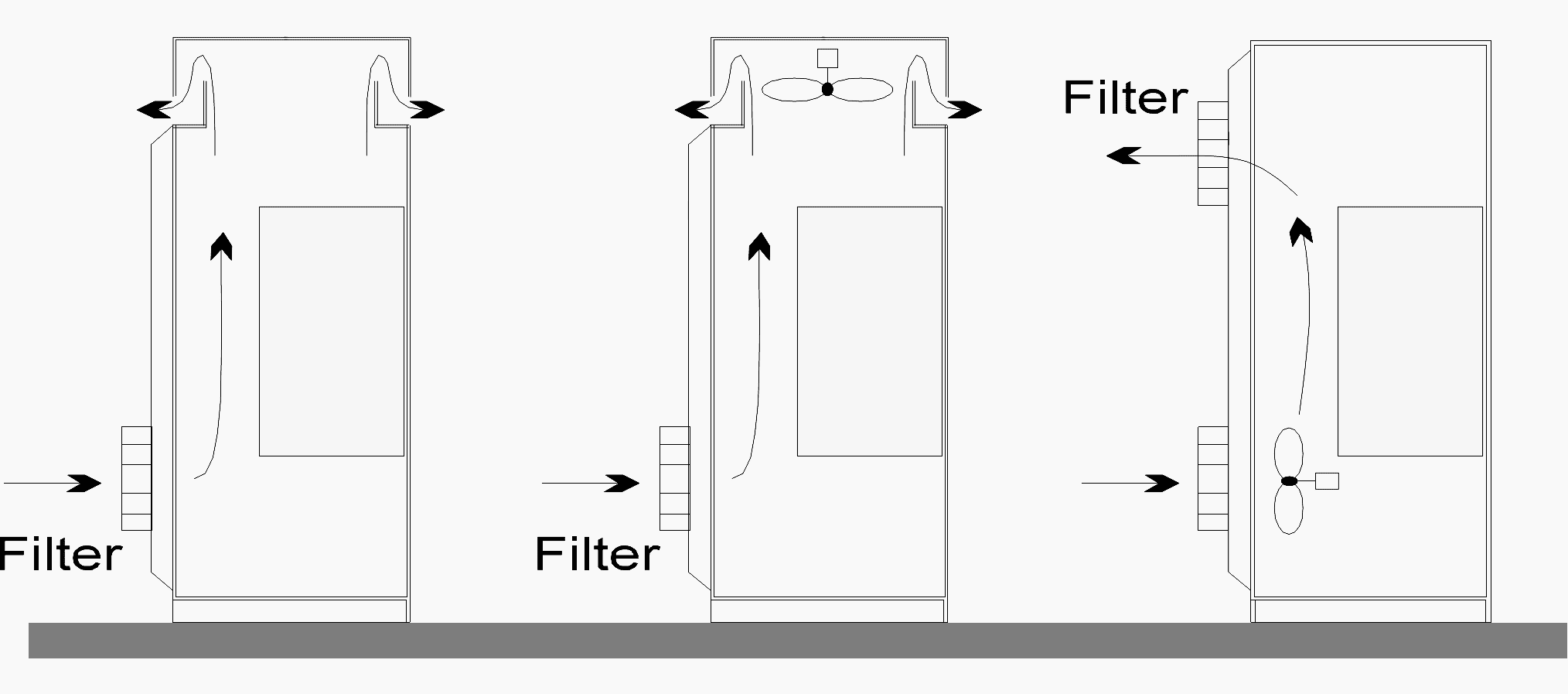
The enclosure can be smaller if some additional ventilation is provided to exchange air between the inside and outside of the cubicle. There are several ventilation techniques commonly used with converters, but they mainly fall into two categories:
Natural ventilation
Relies on the convectional cooling airflow through vents near the bottom of the cubicle and near the top, the ‘chimney’ effect.
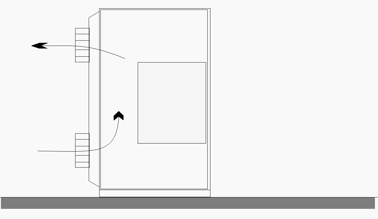
Forced ventilation
Relies on cooling airflow assisted by a fan located either near the top or the bottom of the cubicle. It is difficult to maintain a high IP rating with ventilated cubicles, so ventilated cubicles need to be located in a protected environment, such as a dust-free equipment room.
The required airflow can be calculated from the following formula:
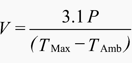
where:
- V – Required airflow in m3 per hour
- P – Power loss of heat producing equipment in watts
- TMax – Maximum permissible operating temperature of converter in °C
- TAmb – Maximum external ambient temperature in °C
Example
Calculate the airflow ventilation requirements of the 22 kW converter used in the example above, using the same assumptions. The required airflow to maintain adequate cooling:
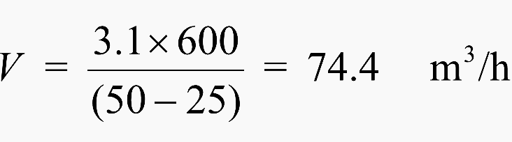
An airflow of 75 m3/h is necessary to remove the heat generated inside the enclosure by the converter and to transfer it to the outside. In this case, the dimensions of the cubicle are based purely on the minimum physical dimensions required for the converter and any other equipment mounted in the cubicle.
This airflow could be achieved by the convectional flow of air provided that the size of the top/bottom openings are large enough and the resistance to airflow is not unnecessarily restricted by dust-filter pads. Alternatively, a fan assisted ventilation system would be necessary to deliver the required airflow.
Alternative mounting arrangements
One of the main problems associated with the ventilation of converter cubicles is that it is very difficult to achieve a high IP rating with a ventilated cubicle! In addition, if filters are used, an additional maintenance problem is introduced, the filters need to be checked and replaced on a regular basis.
Most of the heat generated by a converter is associated with the power electronic components, such as the rectifier module, inverter module, capacitors, reactor and power supply. These items are usually mounted onto the heat sink base of the converter and most of the heat will be dissipated from the surfaces of this heat sink.
The digital control circuits do not generate very much heat, perhaps a few watts.

If the heat sink is recessed through the back mounting plane of the enclosure, most of the heat will be dissipated to the environment external to the cubicle. The portion of the converter with the control circuits remain within the enclosure. With a suitable seal around the converter, the enclosure can be relatively small and rated at >IP54 without the
need for forced or convectional airflow ventilation.
Figure 3 shows a typical mounting arrangement of this type of converter with the heat sinks projecting into a cooling duct.
Reference // Practical Variable Speed Drives and Power Electronics by Malcolm Barnes (Purchase hardcover from Amazon)
Related electrical guides & articles


Edvard Csanyi
Hi, I'm an electrical engineer, programmer and founder of EEP - Electrical Engineering Portal. I worked twelve years at Schneider Electric in the position of technical support for low- and medium-voltage projects and the design of busbar trunking systems.I'm highly specialized in the design of LV/MV switchgear and low-voltage, high-power busbar trunking (<6300A) in substations, commercial buildings and industry facilities. I'm also a professional in AutoCAD programming.
Profile: Edvard Csanyi

NIce info ….