
Estimated Study Time: 10 minutes
Four Sensor ‘Poors’ To Avoid
Generally speaking, there are four ‘Poors’ that can lead to incorrectly installing instrumentation sensors:
 Installing Sensors Incorrectly As a Mistake #2 In Instrumentation (photo credit: polycontrols.com)
Each of above sensor ‘poors’ are described below, and by the way… have you read what is the mistake No.1 in an industrial instrumentation?
1. Sensor Placement
The best sensor can yield disappointing results if not installed correctly. Magmeters, for example, tend to generate noisy signals if the flow they’re measuring is turbulent. Bends, junctions, and valves in a pipe can all cause turbulence, thus magmeters work best when installed in sections of straight pipe.
Temperature sensors are also sensitive to placement. Even a highly accurate RTD tucked in the corner of a mixing chamber will only be able to detect the temperature of its immediate vicinity. If the mixing of the material in the chamber is incomplete, that local temperature may or may not represent the temperature of the material elsewhere in the chamber.
Local temperature issues are the classic mistake that home heating contractors often make when installing household thermostats.
A mounting location closest to the furnace may be convenient for wiring purposes, but if that spot happens to be in a hallway or other dead air space, the thermostat will not be able to determine the average temperature elsewhere in the house. It will only be able to maintain the desired temperature in its immediate vicinity. The rest of the house may end up roasting or freezing.
2. Controller performance // Poor control
Poor control also results when a sensor is installed too far away from the associated actuator. A distant sensor may not be able to measure the effects of the actuator’s last move in time for the controller to make an educated decision about what to do next.
Process of flattening hot steel
For example, consider the process of flattening hot steel into uniform sheets by means of two opposing rollers (see Figure 1 above). A thickness sensor downstream from the rollers gauges the sheet and causes the controller to apply either more or less pressure to compensate for any out-of-spec thickness.
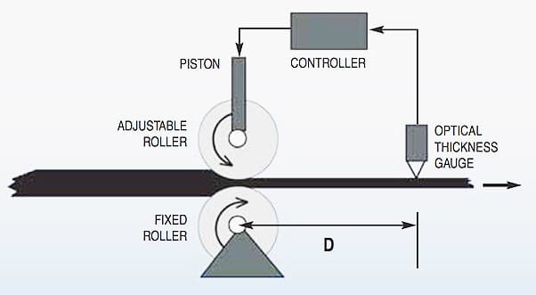
Figure 1 // In this steel rolling example, D is the distance between the steel rollers and the thickness gauge downstream. If D is too large, the controller will take too long to correct thickness errors and may even make matters worse by becoming impatient.
Ideally, the thickness sensor should be located adjacent to the rollers to minimize the time between a change in roller pressure and the resulting change in the thickness measurement. Otherwise, the controller will not be able to detect any mistakes it may have been making soon enough to prevent even more of the sheet from turning out too thick or thin.
Worse still, an appreciable dead time between the controller’s actions and the resulting effects on the steel can cause the controller to become impatient. It will see no results from an initial control move, so it will make another and another until some change begins to appear in the measurements reported by the sensor.
By that time, the controller’s cumulative efforts will have already overcompensated for the original error, causing an error in the opposite direction.
Of course, overall process performance considerations aren’t limited to how well the sensor feeds data to the controller during operation. Other factors to consider include ease of installation and time spent on the selection process, set up routines, and any labor-intensive maintenance. Fortunately, some instrumentation vendors design their sensors to accommodate such challenges, thereby improving performance before the system even goes online.
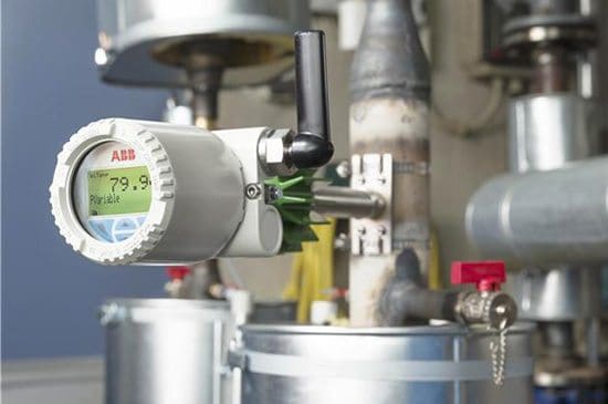
ABB, for instance, offers a swirl flowmeter that significantly reduces the need to install special upstream and downstream devices to accurately measure the flow through a pipe.
3. Poor Protection
A steel mill is also a classic example of a harsh environment that can destroy inadequately protected sensors. Fortunately, the hazards posed by a manufacturing process are generally obvious and can often be overcome by installing a shield or choosing a rugged instrument.
Often overlooked, however, are the effects of weather. Outdoor instruments can take quite a beating from rain, snow, hail, and falling ice. Over time, outdoor instruments can fail slowly unless enclosed in appropriate housings.
But even the housings themselves can cause problems for the enclosed instruments, particularly temperature sensors. If an RTD or thermocouple is mounted on the same piece of metal that supports the housing, the housing will work like a heat sink when the ambient temperature drops low enough. It will tend to draw heat out of the sensor and artificially lower its reading.
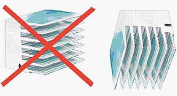
Figure 2 // Even the orientation of an instrument can affect its performance. Here, the sensor is enclosed in a housing designed to dissipate the heat it generates. The fins must be mounted vertically to allow warm air to escape.
Conversely, if a housing is equipped with fins intended to draw heat out of the enclosed sensor during warm weather, the fins must be mounted vertically. Otherwise, the warm air around the fins will not be able to rise away from the housing (see Figure 2 above).
4. Ground loops // Poor grounding
While it’s generally a good practice to insulate a sensor from the thermodynamic effects of its surroundings, it’s absolutely critical to establish electrical isolation. The most common electrical problems due to poor installation are ground loops.

Figure 3 // Instruments must be grounded to provide a reference voltage for the data signals they generate. Relying on earth ground is risky since not all of the earth shares the same electrical potential. The resulting currents will interfere with the sensors’ signals.
Ground loops occur when an extraneous current flows through the instrumentation wiring between two points that are supposed to be at the same voltage, but aren’t (see Figure 3). The resulting electrical interference can cause random fluctuations in the sensors’ output and may even damage the sensors themselves.
Interestingly, the best way to isolate a plant’s instruments from ground loop currents is to connect them together at one master grounding point.
If that’s not possible, a grid of grounding points must be spread throughout the plant, making sure that all points on the grid are at the same electrical potential. Insecure connections and inadequate wires can cause a voltage imbalance in the grid and ground loops between the instruments connected to it.
Reference // The four biggest mistakes in instrumentation – ABB Control Engineering
Related electrical guides & articles


Edvard Csanyi
Hi, I'm an electrical engineer, programmer and founder of EEP - Electrical Engineering Portal. I worked twelve years at Schneider Electric in the position of technical support for low- and medium-voltage projects and the design of busbar trunking systems.I'm highly specialized in the design of LV/MV switchgear and low-voltage, high-power busbar trunking (<6300A) in substations, commercial buildings and industry facilities. I'm also a professional in AutoCAD programming.
Profile: Edvard Csanyi

Hi
Thanks for providing instrumentation and control articles.
Hi, Many Thanks for providing instrumentation and control articles (Good/nice Articles) …