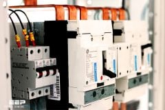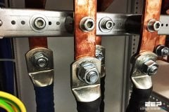
The reason for using insulating materials is to separate electrically the conducting parts of equipment from each other and from earthed components. Earthed components may include the mechanical casing or structure that is necessary to enable the equipment to be handled and to operate. Whereas the ‘active’ parts of the equipment play a useful role in its operation, the insulation is in many ways a necessary evil.
For example in an electric motor the copper of the winding and the steel core making up the magnetic circuit are the active components and both contribute to the power output of the motor; the insulation which keeps these two components apart contributes nothing, in fact it takes up valuable space and it may be considered by the designer as not much more than a nuisance.
For these reasons, insulating materials have become a design focus in many types of electrical equipment, with many companies employing specialists in this field and carrying out sophisticated life testing of insulation systems. Such is the importance attached to this field that major international conferences on the subject are held reg-ularly, for instance by the IEEE in USA, IEE and Electrical Insulation Association (EIA) in UK and the European Electrical Insulation Association (EEIM) in Europe, all of which publish the papers presented. Conferences are also held in Canada, India and South Africa.
The simplest way to define an insulating material is to state what it is not. It is not a good conductor of electricity and it has a high electrical resistance that decreases with rising temperature, unlike conductors.
The following are the most important properties of insulating materials:
- Volume resistivity, which is also known as specific resistance.
- Relative permittivity (or dielectric constant), which is defined as the ratio of the electric flux density produced in the material to that produced in vacuum by the same electric field strength. Relative permittivity can be expressed as the ratio of the capacitance of a capacitor made of that material to that of the same capacitor using vacuum as its dielectric.
- Dielectric loss (or electrical dissipation factor), which is defined as the ratio of the power loss in a dielectric material to the total power transmitted through it. It is given by the tangent of the loss angle and is commonly known as tan delta.
The volume resistivity, relative permittivity and tan delta values for a range of insu-lating materials are shown in Table 1.
Representative properties of typical insulating materials
| Table 1 | Volume resistivity (Ωm) | Relative permittivity | Tan delta (at 50 Hz) |
| Vacuum | Infinity | 1.0 | 0 |
| Air | Infinity | 1.0006 | 0 |
| Mineral insulating oil | 1011–1013 | 2.0 – 2.5 | 0.0002 |
| Pressboard | 108 | 3.1 | 0.013 |
| Dry paper | 1010 | 1.9 – 2.9 | 0.005 |
| Oiled paper | – | 2.8 – 4.0 | 0.005 |
| Porcelain | 1010–1012 | 5.0 – 7.0 | – |
| E-glass | 1016 | 6.1 – 6.7 | 0.002 – 0.005 |
| Polyester resin | 1014–1016 | 2.8 – 4.1 | 0.008 – 0.041 |
| Epoxy resin | 1012–1015 | 3.5 – 4.5 | 0.01 |
| Mica | 1011–1015 | 4.5 – 7.0 | 0.0003 |
| Micapaper | 1013–1017 | 5.0 – 8.7 | 0.0003 |
| PETP film | 1018 | 3.3 | 0.0025 |
| Aramid paper | 1016 | 2.5 – 3.5 | 0.005 – 0.020 |
| Epoxy glass laminate | – | 4.5 – 4.7 | 0.008 |
| Silicone glass laminate | – | 4.5 – 6.0 | 0.003 |
| Polystyrene | 1015 | 2.6 | 0.0002 |
| Polyethylene | 1015 | 2.3 | 0.0001 |
| Methyl methacrylate | 1013 | 2.8 | 0.06 |
| Polyvinyl chloride | 1011 | 5.0 – 7.0 | 0.1 |
| Fused quartz | 1016 | 3.9 | – |
The most important characteristic of an insulating material is its ability to with-stand electric stress without breaking down. This ability is sometimes known as its dielectric strength, and is usually quoted in kilovolts per millimetre (kV/mm).
Another significant aspect of all insulating materials that dominates the way in which they are categorized is the maximum temperature at which they will perform satisfactorily. Generally speaking, insulating materials deteriorate over time more quickly at higher temperatures and the deterioration can reach a point at which the insulation ceases to perform its required function. This characteristic is known as ageing, and for each material it has been usual to assign a maximum temperature beyond which it is unwise to operate if a reasonable life is to be achieved. The main gradings or classes of insulation as defined in IEC 60085:1984 and its UK equivalent BS 2757:1986(1994) are listed in Table 2.
Where a thermal class is used to describe an item of electrical equipment, it normally represents the maximum temperature found within that product under rated load and other conditions. However, not all the insula-tion is necessarily located at the point of maximum temperature, and insulation with a lower thermal classification may be used in other parts of the equipment.
Table 2 – Thermal classes for insulation
| Thermal class | Operating temperature (°C) |
| Y | 90 |
| A | 105 |
| E | 120 |
| B | 130 |
| F | 155 |
| H | 180 |
| 200 | 200 |
| 220 | 220 |
| 250 | 250 |
The ageing of insulation depends not only on the physical and chemical properties of the material and the thermal stress to which it is exposed, but also on the presence and degree of influence of mechanical, electrical and environmental stresses. The pro-cessing of the material during manufacture and the way in which it is used in the com-plete equipment may also significantly affect the ageing process.
The definition of a useful lifetime will also vary according to the type and usage of equipment; for instance the running hours of a domestic appliance and a power station generator will be very different over a 25-year period. All of these factors should therefore influence the choice of insulating material for a particular application. There is therefore a general movement in the development of standards and methods of testing for insulating materials towards the consideration of combinations of mate-rials or insulating systems, rather than focusing on individual materials. It is not uncommon to consider life testing in which more than one form of stress is introduced; this is known as multifunctional or multifactor testing.
Primary insulation is often taken to mean the main insulation, as in the PVC coat-ing on a live conductor or wire. Secondary insulation refers to a second ‘line of defence’ which ensures that even if the primary insulation is damaged, the exposed live com-ponent does not cause an outer metal casing to become live. Sleeving is frequently used as a secondary insulation.
Insulating materials may be divided into basic groups which are solid dielectrics, liquid dielectrics, gas and vacuum. Each is covered separately in the following sections.


What is the dielectric strength of G-10-Gerolite ?
excellent article thank you very much!