
Estimated Study Time: 11 minutes
Interconnection transformers
Interconnection transformers are used to interface a distribution generation (DG) unit with an existing power system, and to provide the necessary isolation. Utilities recommend using an interconnection transformer to eliminate possible zero sequence or dc components in the generated voltages, and to increase the protection.
 The impact of interconnection transformer on the protection of the utility system with DG
Furthermore, the transformer can be considered as a filter inductor, hence, it improves the quality of the current injected by the DG unit. Transformer connections play a key role in how the DG unit affects the utility system and how the utility system affects the DG unit.
There is no universally accepted “best” connection for the interconnection transformer. Each connection has its own advantages and disadvantages. The advantages and disadvantages of the various configurations depend on the local installation, the generator, and the utility system grounding requirements.
Typical Transformer Connections
Five typical transformer connections are widely used to interconnect DG’s to the utility system; namely they are:
- Delta (HVS) / Delta (LVS),
- Delta (HVS) / Wye-Gnd (LVS),
- Wye-Ungnd (HVS) / Delta (LVS),
- Wye-Gnd (HVS) / Delta (LVS) and
- Wye-Gnd (HVS) / Wye-Gnd (LVS),
Where (HVS) indicates the primary winding and (LVS) indicates the secondary winding.
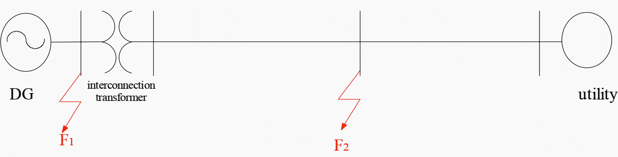
To illustrate the impact of each transformer connection on the system protection, let us consider a simple system as shown in Figure 1 A DG unit it interfaced to the utility via an interconnection transformer as depicted in Figure 1.
Two possible locations (F1 and F2) for a single-line to ground fault are considered.
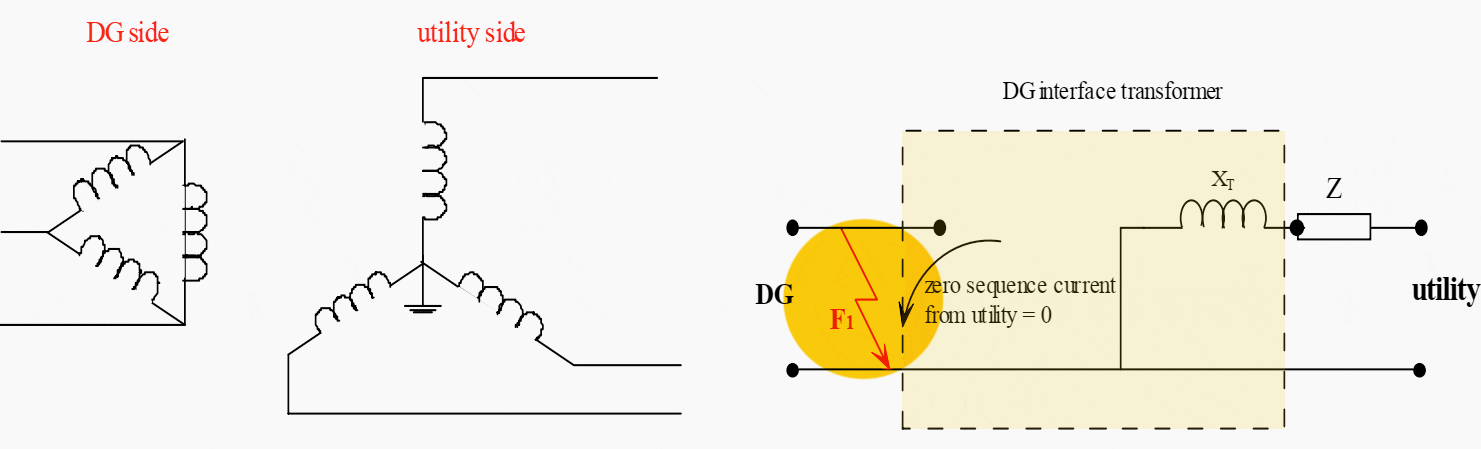
1. Ungrounded Primary Side (HVS)
Consider the first three connections with ungrounded primary side (HVS):
- Delta (HVS) / Delta (LVS),
- Delta (HVS) / Wye-Gnd (LVS) and
- Wye-Ungnd (HVS) / Delta (LVS)
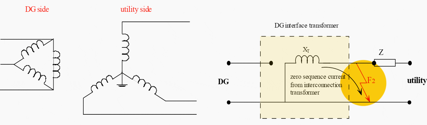
Figure 2 shows the zero sequence current contributions from these connections in the case of a ground fault at F2 in the sample distribution system shown in Figure 1. It is clear form Figure 2 that for a ground fault at F2, there will be no path for the zero sequence current from the DG and interconnection transformer side.
Another advantage of these connections is that any ground fault on the secondary of the interconnection transformer (at F1) will not be seen by the utility protection system and as result. The ground coordination system will not be affected.

The major concern with an interconnection transformer with an ungrounded primary winding is that after the utility breaker is tripped for a permanent ground fault, the system will be fed from an ungrounded source.
This subjects the unfaulted phases to an overvoltage that will approach the line-to-line voltage. This occurs if the DG is near the capacity of the load on the feeder when utility breaker trips. The resulting overvoltages will saturate the transformer, which normally operates at the knee of the saturation curve.
Many utilities use ungrounded interconnection transformers only if a 200% or more overload on the DG occurs when utility breaker trips.
To understand how DG can generate an overvoltage during a ground fault, consider the situation given in Figure 3. In this example, we have a four-wire multigrounded-neutral distribution circuit that has one conductor (phase-A) faulted to the neutral.
Once this occurs, a high fault current is generated until the substation circuit breaker opens. Once the substation source is cleared, and the DG is still feeding the system, then the voltage of the neutral (earth) becomes that of phase A of the DG.

Any loads or equipment connected between an unfaulted phase (C or B) and neutral will suddenly be subjected to voltages that are equivalent to the line-to-line voltage that is about 1.73 times higher than the pre-fault voltage.
The distribution transformers serving customers on these phases are connected line to neutral and thus would saturate and subject customer equipment to such overvoltages.
Moreover, since the nominal pre-fault voltage may be as high as 105% due to the ANSI voltage regulation allowance, as a result, the voltage may reach 182% of nominal during the faulted condition, which increases of possibility damaging the equipment.
2. Grounded Primary Side (HVS)
2.1 Wye-Grounded (Primary) / Delta (Secondary)
Consider a Wye-Grounded (Primary)/Delta (Secondary) connection. For a ground fault at F1 in the system of Figure 1, the utility will not contribute any zero sequence current to the fault as shown in Figure 4, and as result, this arrangement prevents the utility protection system to respond to ground faults at the DG side.
However, the disadvantage of this arrangement is that it acts as a zero sequence current source. Hence, establishing a zero sequence current for ground faults on the distribution system. This is the case for a ground fault at F2 in the system in Figure 1. This could have a significant impact on the utility’s ground relay coordination as shown in Figure 5.
Also, this zero-sequence current from the high voltage side will circulate in the delta winding on the low voltage side, and possibly causing heating problems within the transformer.
A commonly practiced solution to this problem is to place grounding impedance in the high-side neutral connection to limit the flow of excessive circulating currents. The ground impedance should be high enough to limit the circulating current but low enough to maintain effective grounding of the DG unit.
In addition, any unbalanced load on the distribution circuit would normally return to ground through the utility transformer neutral. With the addition of the generator interconnection transformer, this unbalance will be divided between the utility transformer neutral and the generator interconnection transformer.
During serious unbalance conditions such as a blown lateral fuse, the load carrying capability of the interconnection transformer can be reduced.
The use of a grounded-wye winding on the high side and delta on the low side has the advantage of limiting the overvoltages that can be developed when the utility beaker opens; thereby sparing lightning arresters and feeder loads from damage.
2.2 Wye-Grounded (Primary) / Wye-Grounded (Secondary)
Consider a Wye-Grounded (Primary)/Wye-Grounded (Secondary) connection. For a ground fault at F1 in the system of Figure 1, the DG together with the utility will feed the fault as shown in Figure 6.
As a result, the fault current level will increase and this may affect the ground relay coordination. The same impact will be yielded for a ground fault at F2, as shown in Figure 7.

The main advantage for this connection is that no overvoltages will be developed when the utility beaker opens (for a solidly grounded connection).
The major disadvantage of this connection is that it provides a source of unwanted ground current for utility feeder faults similar to that described in the previous section.

Source: Protection coordination planning with distributed generation by CETC Varennes – Energy Technology and Programs Sector (Dr. Tarek K. Abdel-Galil, Ahmed E.B. Abu-Elanien, Eng., Dr. Ehab F. El-Saadany, Dr. Adly Girgis, Yasser A.-R. I. Mohamed, Eng., Dr. Magdy M. A. Salama, Dr. Hatem H. M. Zeineldin at Qualsys Engco. Inc.)
Related electrical guides & articles


Edvard Csanyi
Hi, I'm an electrical engineer, programmer and founder of EEP - Electrical Engineering Portal. I worked twelve years at Schneider Electric in the position of technical support for low- and medium-voltage projects and the design of busbar trunking systems.I'm highly specialized in the design of LV/MV switchgear and low-voltage, high-power busbar trunking (<6300A) in substations, commercial buildings and industry facilities. I'm also a professional in AutoCAD programming.
Profile: Edvard Csanyi

The fig 2 diagrams naming are interchanged. Good article.
Please post something about diesel generator breaker failure to open(mechanical lock out) and setup of protections in the system (upsteram/downstream)
Please can you post something about protecting a system from generator breaker mechanical failure to open(upstream / downstream ) and share your experiences
Your articles very educative keep up
Muchas gracias por tan excelente informe OK