
Estimated Study Time: 22 minutes
Transmission media & communications
The transmission media that provide the communication links involved in relay protection signalling are private pilots, rented pilots or channels, power line carrier, radio and the newest and the most advanced technology – optical fibres.
 Interference and noise affecting transmission media in protection signalling
Historically, pilot wires and channels (discontinuous pilot wires with isolation transformers or repeaters along the route between signalling points) have been the most widely used due to their availability, followed by Power Line Carrier Communications (PLCC) techniques and radio.
In recent years, fibre-optic systems have become the usual choice for new installations, primarily due to their complete immunity from electrical interference.
The use of fibre-optic cables also greatly increases the number of communication channels available for each physical fibre connection and thus enables more comprehensive monitoring of the power system to be achieved by the provision of a large number of communication channels.
- Private Pilot Wires and Channels
- Rented Pilot Wires and Channels
- Power Line Carrier Communications Techniques
- Radio Channels
- Optical Fibre Channels
1. Private Pilot Wires and Channels
Pilot wires are continuous copper connections between signalling stations, while pilot channels are discontinuous pilot wires with isolation transformers or repeaters along the route between signalling stations.
They may be laid in a trench with high voltage cables, laid by a separate route or strung as an open wire on a separate wood pole route.
For short distances, no special measures are required against interference, but over longer distances, special send and receive relays may be required to boost signal levels and provide immunity against induced voltages from power circuits, lightning strikes to ground adjacent to the route, etc.
Isolation transformers may also have to be provided to guard against rises in substation ground potential due to earth faults.
The capacity of a link can be increased if multiplexing techniques are used to run parallel signalling systems but some utilities prefer the link to be used only for protection signalling.
Private pilot wires or channels can be attractive to a utility running a very dense power system with short distances between stations.
2. Rented Pilot Wires and Channels
These are rented from national communication authorities and, apart from the connection from the relaying point to the nearest telephone exchange, the routing is through cables forming part of the national communication network.
An economic decision has to be made between the use of private or rented pilots. It’s very important to know that if private pilots are used, the owner has complete control, but bears the cost of installation and maintenance.
If rented pilots are used, most of these costs are eliminated, but fees must be paid to the owner of the pilots and the signal path may be changed without warning. This may be a problem in protection applications where signal transmission times are critical.
The chance of voltages being induced in rented pilots is smaller than for private pilots, as the pilot route is normally not related to the route of the power line with which it is associated.
However, some degree of security and protection against induced voltages must be built into signalling systems. Station earth potential rise is a significant factor to be taken into account and isolation must be provided to protect both the personnel and equipment of the communication authority.
Communication between relaying points may be over a two-wire or four-wire link. Consequently the effect of a particular human action, for example an incorrect disconnection, may disrupt communication in one direction or both.
The signals transmitted must be limited in both level and bandwidth to avoid interference with other signalling systems. The owner of the pilots impose standards in this respect that may limit transmission capacity or transmission distance, or both.
With a power system operating at, say, 132 kV, where relatively long protection signalling times are acceptable, signalling has been achieved above speech together with metering and control signalling on an established control network.
Consequently the protection signalling was achieved at very low cost.
High voltage systems (220 kV and above), have demanded shorter operating times and improved security, which has led to the renting of pilot links exclusively for protection signalling purposes.
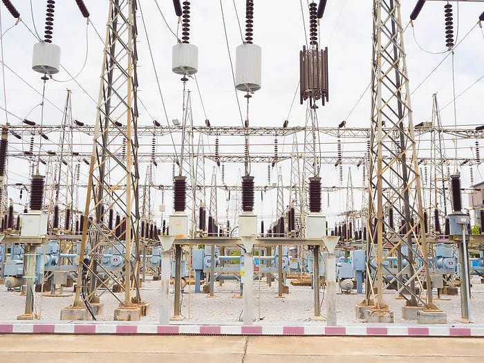
3. Power Line Carrier Communications Techniques
Where long line sections are involved, or if the route involves installation difficulties, the expense of providing physical pilot connections or operational restrictions associated with the route length require that other means of providing signalling facilities are required.
High voltage capacitors are used, along with drainage coils, for the purpose of injecting the signal to and extracting it from the line. Injection can be carried out by impressing the carrier signal voltage between one conductor and earth or between any two phase conductors.
The basic units can be built up into a high pass or band pass filter as shown in Figure 3.
The high voltage capacitor is tuned by a tuning coil to present a low impedance at the signal frequency. The parallel circuit presents a high impedance at the signal frequency while providing a path for the power frequency currents passed by the capacitor.
It is necessary to minimize the loss of signal into other parts of the power system, to allow the same frequency to be used on another line. This is done with a ‘line trap‘ or ‘wave trap‘, which in its simplest form is a parallel circuit tuned to present a very high impedance to the signal frequency.
It is connected in the phase conductor on the station side of the injection equipment.
The single frequency line trap can be treated as an integral part of the complete injection equipment to accommodate two or more carrier systems.
However, difficulties may arise in an overall design because at certain frequencies the actual station reactance, which is normally capacitive, tunes with the trap which is inductive below its resonant frequency. The result is a low impedance across the transmission path, preventing operation at these frequencies.
This situation can be avoided by using an independent ‘double frequency‘ or ‘broad-band’ trap.
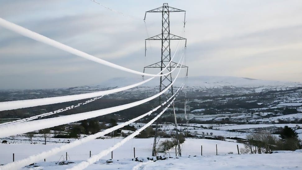
The high frequency transmission characteristics of power circuits are good the loss amounting to 0.02 to 0.2 dB per kilometre depending upon line voltage and frequency. Line attenuation is not affected appreciably by rain, but serious increase in loss may occur when the phase conductors are thickly coated with hoar-frost or ice.
Attenuations of up to three times the fair weather value have been experienced.
Receiving equipment commonly incorporates automatic gain control (AGC) to compensate for variations in attenuation of signals.
High noise levels arise from lightning strikes and system fault inception or clearance. Although these are of short duration, lasting only a few milliseconds at the most, they may cause overloading of power line carrier receiving equipment.
3.1 Application Considerations
Signalling systems used for intertripping in particular must incorporate appropriate security features to avoid maloperation. The most severe noise levels are encountered with operation of the line isolators, and these may last for some seconds.
Although maloperation of the associated teleprotection scheme may have little operational significance, since the circuit breaker at one end at least is normally already open, high security is generally required to cater for noise coupled between parallel lines or passed through line traps from adjacent lines.
A protection signal boost facility can be employed to cater for an increase in attenuation of this order of magnitude, to maintain an acceptable signal-to-noise ratio at the receiving end, so that the performance of the service is not impaired.
Most direct intertrip applications require signalling over a healthy power system, so boosting is not normally needed. In fact, if a voice frequency intertrip system is operating over a carrier bearer channel, the dynamic operating range of the receiver must be increased to accommodate a boosted signal.
This makes it less inherently secure in the presence of noise during a quiescent signalling condition.
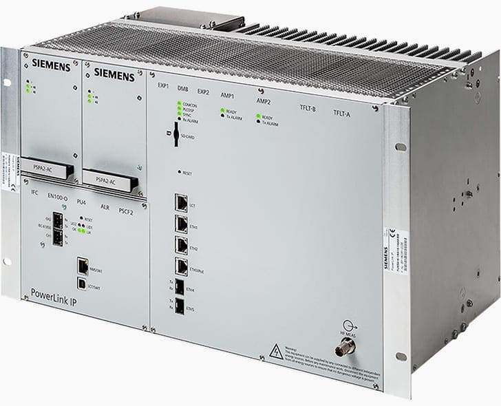
3.2 Digital Power Line Carrier
The latest power line carrier equipment allows analogue, digital and mixed-mode communication. Digital communication up to 128 kbits/s can be achieved using a 16 kHz bandwidth.
Low-latency Ethernet bridging facilities are a cost-effective communications solution for substations that have no access to any fibre network.
4. Radio Channels
At first consideration, the wide bandwidth associated with radio frequency transmissions could allow the use of modems operating at very high data rates. Protection signalling commands could be sent by serial coded messages of sufficient length and complexity to give high security, but still achieve fast operating times.
In practice, it is seldom economic to provide radio equipment exclusively for protection signalling, so standard general-purpose telecommunications channel equipment is normally adopted.
Multiplexing techniques allow several channels to share the common bearer medium and exploit the large bandwidth
In addition to voice frequency channels, wider bandwidth channels or data channels may be available, dependent on the particular system. For instance, in analogue systems using frequency division multiplexing, normally up to 12 voice frequency channels are grouped together in basebands at 12-60 kHz or 60-108 kHz, but alternatively the baseband may be used as a 48 kHz signal channel.
Modern digital systems employing pulse code modulation and time division multiplexing usually provide the voice frequency channels by sampling at 8 kHz and quantising to 8 bits. Alternatively, access may be available for data at 64 kbits/s (equivalent to one voice frequency channel) or higher data rates.
Radio systems are well suited to the bulk transmission of information between control centres and are widely used for this. When the route of the trunk data network coincides with that of transmission lines, channels can often be allocated for protection signalling.
More generally, radio communication is between major stations rather than the ends of individual lines, because of the need for line-of-sight operation between aerials and other requirements of the network.
Radio channels are not affected by increased attenuation due to power system faults, but fading has to be taken into account when the signal-to-noise ratio of a particular installation is being considered.
Most of the noise in such a protection signalling system is generated in the radio equipment.
A polluted atmosphere can cause radio beam refraction that interferes with efficient signalling. The height of aerial tower should be limited, so that winds and temperature changes have the minimum effect on their position.
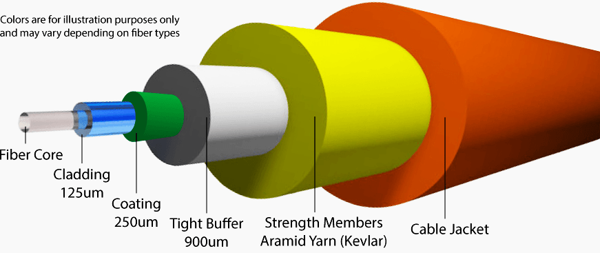
5. Optical Fibre Channels
Optical fibres are fine strands of glass, which behave as wave guides for light. This ability to transmit light over considerable distances can be used to provide optical communication links with enormous information carrying capacity and an inherent immunity to electromagnetic interference.
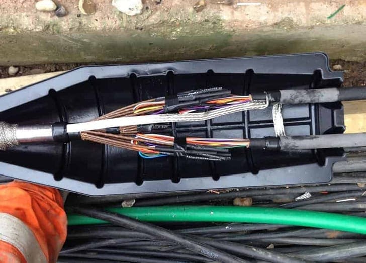
A practical optical cable consists of a central optical fibre which comprises core, cladding and protective buffer coating surrounded by a protective plastic oversheath containing strength members which, in some cases, are enclosed by a layer of armouring.
To communicate information a beam of light is modulated in accordance with the signal to be transmitted. This modulated beam travels along the optical fibre and is subsequently decoded at the remote terminal into the received signal.
On/off modulation of the light source is normally preferred to linear modulation since the distortion caused by non-linearities in the light source and detectors, as well as variations in received light power, are largely avoided.
Within the fibre there are many modes of propagation with different optical paths that cause dispersion of the light signal and result in pulse broadening. The degrading of the signal in this way can be reduced by the use of ‘graded index’ fibres that cause the various modes to follow nearly equal paths.
The distance over which signals can be transmitted is significantly increased by the use of ‘monomode’ fibres that support only one mode of propagation.
Optical fibre channels allow communication at data rates of hundreds of megahertz over a few tens of kilometres, however, repeaters are needed for greater distances. An optical fibre can be used as a dedicated link between two items of terminal equipment or as a multiplexed link that carries all communication traffic such as voice, telecontrol and protection signalling.
For protection signalling, the available bandwidth of a link is divided by time division multiplexing (T.D.M.) techniques into several channels, each of 64 kbits/s. Each 64 kbits/s channel is equivalent to one voice frequency channel, which typically uses 8-bit analogue-to-digital conversion at a sampling rate of 8 kHz.
Several utilities sell surplus capacity on their links to telecommunications operators, or they may take the opportunity to increase the data rate in end-to-end applications up to 2 Mbits/s.
The trend of using rented pilot circuits is being reversed as the utilities revert to ownership of the communication circuits that carry protection signalling.
Whilst such fibres can be laid in cable trenches, there is a strong trend to associate them with the conductors themselves by producing composite cables comprising optical fibres embedded in the conductors, either earth or phase.
For overhead lines use of OPGW (Optical Ground Wire) earth conductors is very common, while an alternative is to wrap the optical cable helically around a phase or earth conductor. This latter technique can be used without restringing of the line.
Source: Simon Richards, Steve Potts, Graham Elliott, Michael Bergstrom, Michael Bamber-Network Protection and Application Guide – Protective Relays, Measurement and Control – Alstom Grid
Related electrical guides & articles


Edvard Csanyi
Hi, I'm an electrical engineer, programmer and founder of EEP - Electrical Engineering Portal. I worked twelve years at Schneider Electric in the position of technical support for low- and medium-voltage projects and the design of busbar trunking systems.I'm highly specialized in the design of LV/MV switchgear and low-voltage, high-power busbar trunking (<6300A) in substations, commercial buildings and industry facilities. I'm also a professional in AutoCAD programming.
Profile: Edvard Csanyi

I am Electrical Engineer in India. Your articles are so precious which enable us for learning new era in EE.
Thanks for sharing such information on site.