
Estimated Study Time: 27 minutes
Interlocking Operations
Interlocking systems are critical to the safe and efficient operation of high-voltage substations, ensuring proper sequencing of equipment operations and preventing dangerous scenarios such as simultaneous energization or grounding. This technical article delves into the intricacies of the 380kV interlocking diagram for Dia C02, specifically within the context of the one-and-a-half breaker scheme.
 Interlocking for 380kV GIS Substation: Insights into CB and isolator test and service positions
The article explores key aspects of the interlocking system, starting with an overview of the scheme layout and the role of supporting equipment like busbar earth switches. It provides detailed insights into circuit breaker and isolator configurations, their operations, and associated interlocking logic.
A special emphasis is placed on the standard operating practices, maintenance safety protocols, and the critical role interlocking plays in ensuring system reliability and personnel safety.
Further, the article explores the key features and functionalities of the service and test positions of circuit breakers, outlining the differences and operational requirements.
It also explains the interlocking logic for isolator Q1-1 and its significance in both service and test positions, providing a complete understanding of the system’s design and operational intent.
This guide aims to serve as a practical resource for engineers, technicians, and professionals working in substation operations, enabling them to gain a deeper understanding of 380kV interlocking systems and their importance in modern power systems.
- Understanding the 380kV Interlocking Diagram for Dia C02
- Understanding Circuit Breaker Q01 Interlocking
- Understanding the Service Position of a Circuit Breaker
- Understanding Circuit Breaker Q01 Closing Operations at Service Position
- Understanding the Test Position of a Circuit Breaker
- Circuit Breaker Q01, Close Operation in the Test Position
- Understanding Interlocking Operations for Isolator Q1-1
- Understanding Interlocking Operations for Isolator Q1-2
- BONUS (PDF) 🔗 Download ‘Pre-commissioning Procedures And Formats Substation For Equipment & Protection System’
1. Understanding the 380kV Interlocking Diagram for Dia C02
The interlocking diagram for a 380kV substation employing the one-and-a-half breaker scheme is a comprehensive representation of the system’s operating conditions and interlocking requirements
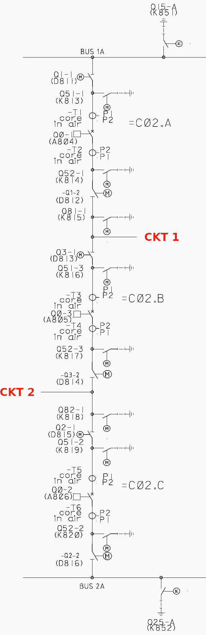
In this scheme, three circuit breakers form the core of the Dia C02 configuration. Circuit breaker Q01, also referred to as C02.A, is connected to Busbar 1A, while circuit breaker Q02, referred to as C02.C, connects to Busbar 2A. The third breaker, Q03, known as C02.B, is positioned as the middle breaker, shared by both circuits.
This arrangement provides flexibility and redundancy, allowing one circuit to remain operational even when the other is isolated for maintenance or in the event of a fault.
This practice ensures that the circuit can be quickly brought back into service when required and simplifies operational processes.
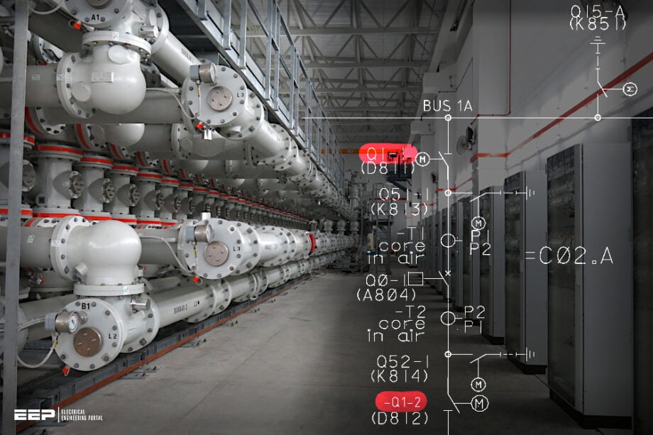
Figure 1 – Dia C02 for one and half breaker scheme
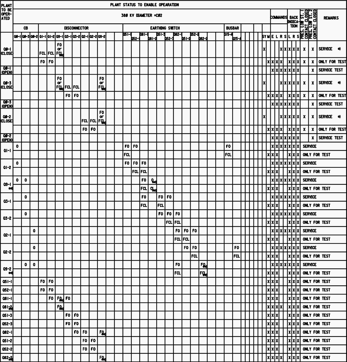
Legends:
- SY = Synchro Check operation need to be check
- M = Maintenance condition & synchro check operation is bypassed
- L = Command can be given when control is at local
- R = Command can be given when control is at Remote
- S = Command can be given when control is at SCADA
- O = Open Status of device
- CL = Close status of device
- FO = Fully Open position, that means that device has completed its operation and not in the intermitted position or under operation.
- FCL = Fully closed position, that means that device has completed its operation and not in the intermitted position or under operation.
- E = Emergency position
- PRES. Low St. 1 = SF6 Low Pressure Stage 1, this is alarm stage
- PRES. Low St. 2 = SF6 Low Pressure Stage 2, this is lockout stage
Figure 2 – Interlocking scheme of Dia C02
2. Understanding Circuit Breaker Q01 Interlocking
Circuit Breaker Q01 is connected to two isolators, Q1-1 and Q1-2, as well as two earth switches, Q51-1 and Q52-1. The interaction between these components ensures safe switching operations and adherence to operational protocols.
Q01 is governed by two separate interlocking tables—one for its closing operations and another for its opening operations, refer to the Figure 2. These interlocks are designed to prevent unsafe switching and protect equipment from damage.
2.1 Circuit Breaker Q01 Open Operation
Unlike closing operations, opening the circuit breaker does not depend on the status of other equipment, such as synchronization or maintenance conditions. However, there is a critical requirement regarding the status of the isolators connected to the circuit breaker.
Isolator Operation Restriction
Circuit Breaker Q01 cannot be operated while the connected isolators, Q1-1 and Q1-2, are in operation. If the circuit breaker is operated during this time, the making or breaking of current could occur through the isolator’s contacts, which are not designed for on-load operations.
Such a scenario could lead to severe damage to the isolator or unsafe conditions.
Related electrical guides & articles


Muhammad Kashif
Muhammad Kashif Shamshad is an Electrical Engineer and has more than 17 years of experience in operation & maintenance, erection, testing project management, consultancy, supervision, and commissioning of Power Plant, GIS, and AIS high voltage substations ranging up to 500 kV HVAC & ±660kV HVDC more than ten years experience is with Siemens Saudi Arabia.Profile: Muhammad Kashif
