
Estimated Study Time: 28 minutes
One-and-a-Half Breaker Scheme
This article delves into various aspects of the one-and-a-half breaker scheme applied to 380kV GIS switchgear, starting with its benefits and operational framework. It further examines the critical interlocking concepts, including open and closed positions, the “under operation” state (dangerous transitional state), and fully open or fully closed positions.
 Interlocking for 380kV GIS Substation: One-and-a-half breaker scheme analysis
Additional interlocking conditions, such as synchro check functions, maintenance modes, emergency conditions, SF6 pressure interlocks, and local versus remote operations, are discussed in detail.
Moreover, the article investigates the scheme’s configuration, nomenclature, and typical operating states, offering insights into its real-world applications and reliability.
By systematically addressing these topics, this article aims to provide a comprehensive understanding of the one-and-a-half breaker scheme, highlighting its significance in achieving robust and flexible EHV substation operations.
Extra-High Voltage (EHV) substations play a pivotal role in modern power transmission networks, where reliability and operational flexibility are paramount. These substations facilitate the efficient transfer of electricity over long distances, ensuring grid stability and minimizing disruptions. Among the various configurations employed in EHV substations, the one-and-a-half breaker scheme stands out as a sophisticated and widely adopted solution.
Its unique design offers unmatched redundancy and operational flexibility, making it a cornerstone of critical transmission systems.
Such flexibility makes the one-and-a-half breaker scheme ideal for high-reliability systems, where uninterrupted power supply is non-negotiable.
- Enhancing Reliability and Flexibility in EHV Substations: The One-and-a-Half Breaker Scheme and Its Interlocking Requirements
- Benefits of the One-and-a-Half Breaker Scheme
- Understanding the Different Operating Conditions in the Interlock Table:
- Basic Concepts: Open and Closed Positions
- Introducing the “Under Operation” State
- Fully Open and Fully Closed Positions
- Additional Interlocking Conditions
- Synchro Check Function
- Maintenance Condition
- Emergency Condition
- SF6 Pressure Level Interlocks
- Local, Remote, and SCADA Operations
- Investigating the One-and-a-Half Breaker Scheme with Typical Two Overhead Lines
- Understanding the Configuration
- Nomenclature of Isolators and Busbars
- Exploring the Operational Roles
- Significance of Nomenclature in Interlocking
- Typical Operating States of the One-and-a-Half Breaker Scheme:
- Attachments (DWG) 🔗 AutoCAD Drawings of Switching Single-Line Diagram and Interlocking Table for 380kV GIS Switchgear
1. Enhancing Reliability and Flexibility in EHV Substations
The One-and-a-Half Breaker Scheme and Its Interlocking Requirements
The one-and-a-half breaker arrangement is a sophisticated and widely used configuration in extra-high voltage (EHV) substations, primarily valued for its reliability, operational flexibility, and enhanced system security. This scheme is often deployed in critical transmission networks where uninterrupted power supply and fault tolerance are paramount.
Understanding its operational framework and interlocking requirements is essential for ensuring safe and efficient substation management.
In a one-and-a-half breaker arrangement, three circuit breakers are used to control two circuits, with the middle breaker shared between them. This configuration allows any single breaker to be taken out of service for maintenance without the need for a bypass arrangement. The design ensures that each circuit remains operational, even when one breaker is out of service, thereby minimizing disruptions to the power system.
This redundancy and flexibility make the scheme highly advantageous in high-reliability transmission systems.
Interlocking requirements in the one-and-a-half breaker scheme are intricate and designed to manage various operational scenarios, such as routine switching, fault isolation, and maintenance activities.
Modern substations implement these interlocking requirements using Intelligent Electronic Devices (IEDs) and SCADA systems that communicate via protocols like IEC 61850. These systems enable real-time monitoring and control, enhancing operational reliability and safety.
Furthermore, proper documentation of interlocking logic and extensive operator training are critical for ensuring effective implementation.
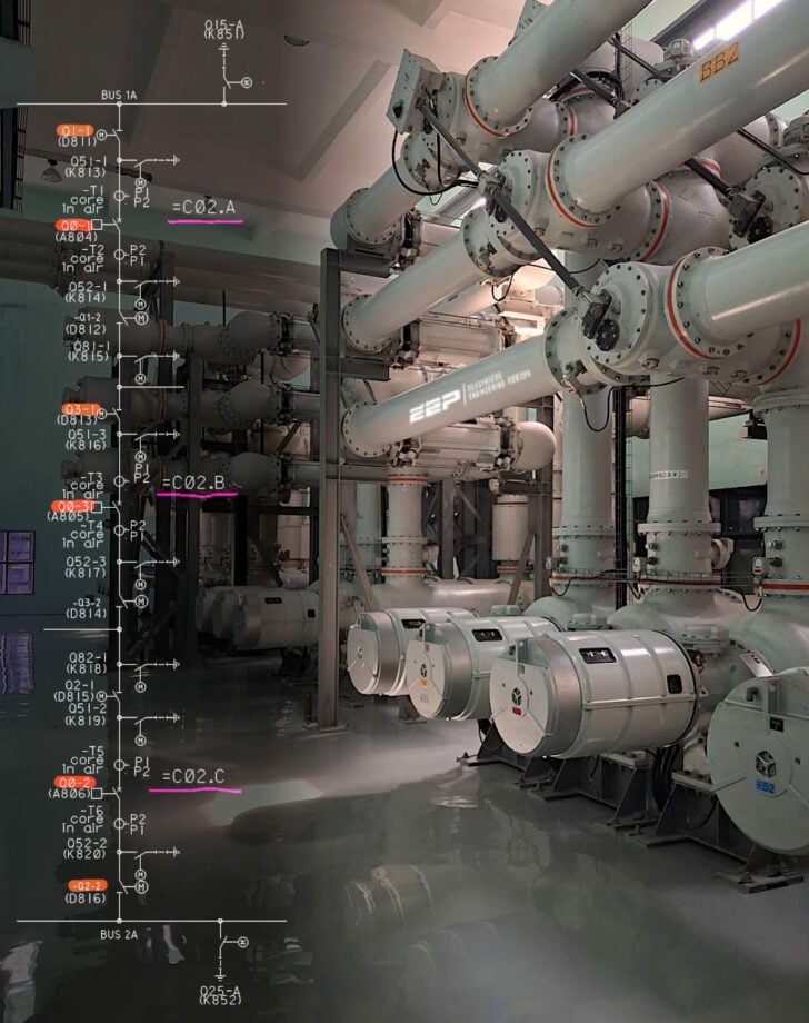
Figure 1 – Switching scheme of 380kV GIS switchgear (click to zoom)
*** Download attachment at the bottom of article: AutoCAD drawing (DWG)
2. Benefits of the One-and-a-Half Breaker Scheme
The one-and-a-half breaker scheme provides significant operational advantages, including:
- Redundancy: The shared tie breaker allows uninterrupted operation of both feeders even when one breaker is out of service.
- Flexibility: Load transfers and fault isolations can be performed seamlessly, minimizing service disruptions.
- Cost Efficiency: By reducing the total number of breakers required compared to other configurations, this scheme offers cost savings without compromising reliability.
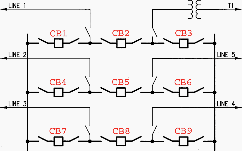
Figure 2 – Representation of one and half breaker scheme
3. Different Operating Conditions in the Interlock Table
Before delving into the detailed aspects of interlocking logic and its application, it is crucial to first understand the various terms and concepts that underpin these mechanisms. Interlocking systems ensure safe operations within substations by coordinating the sequence of equipment operations.
Familiarity with these foundational concepts is essential for engineers and operators alike to grasp the nuances of interlocking tables and their practical applications.
3.1 Basic Concepts: Open and Closed Positions
At its core, the concept of open and closed positions is straightforward. When a device, such as an isolator or an earth switch, is in the open position, it is not connected, and no current flows through it. Conversely, when it is in the closed position, it allows current to flow. Most interlocking conditions rely on these states to enforce operational safety.
For instance, it is a widely understood rule that an isolator should not be operated, nor should an earth switch be engaged, if the isolator is in the closed position. This prevents dangerous electrical arcs or equipment damage.
3.2 Introducing the “Under Operation” State
In addition to the familiar open and closed states, there exists another critical state referred to as the “under operation” state. This state occurs when a device is transitioning from one position to another. For example, consider an isolator in the open position.
If a closing command is issued and all interlocking conditions are satisfied, the isolator begins to move toward the closed position.
Therefore, it is imperative that interlocking logic accounts for this transitional state to prevent unsafe operations.
Figure 3 – Interlocking table for 380kV GIS switchgear (click to zoom)
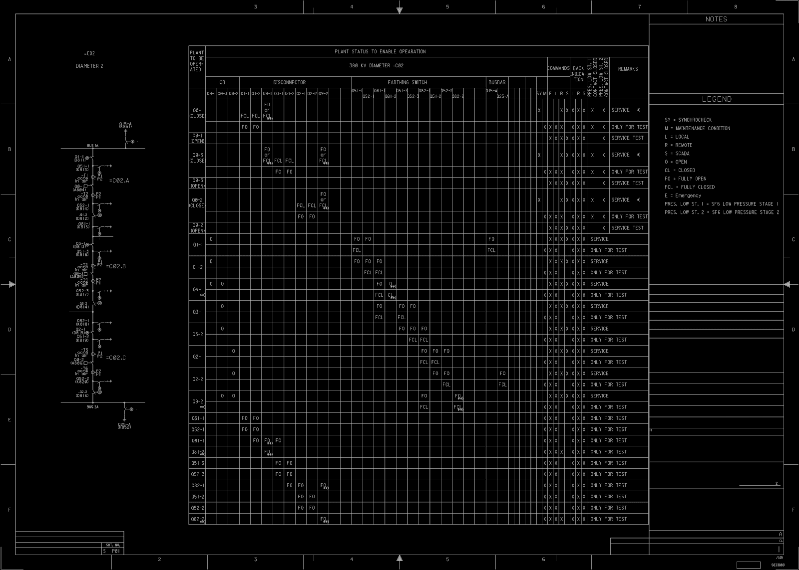
*** Download attachment at the bottom of article: AutoCAD drawing (DWG)
3.3 Fully Open and Fully Closed Positions
To address these considerations, the terms “fully open” and “fully closed” are used to describe the states where a device’s operation has been completed. These terms signify that the isolator or earth switch is either completely disengaged (fully open) or entirely engaged (fully closed). By clearly defining these states, interlocking systems can ensure that operations are carried out safely and effectively.
In subsequent sections, the abbreviations FCL (Fully Closed) and OF (Open Fully) will be used to denote these conditions. Understanding these states and their implications is essential for interpreting interlocking tables and applying the logic to real-world scenarios.
3.4 Additional Interlocking Conditions
In the realm of substation interlocking, understanding additional interlocking conditions is essential to ensure seamless operations and adherence to safety protocols. These conditions address specific scenarios and operational states, adding layers of complexity and functionality to the interlocking logic.
The following sections explore critical interlocking conditions and their implications.
3.5 Synchro Check Function
The synchro check function is a pivotal aspect of interlocking logic, especially concerning circuit breaker operations. This function ensures that the phase angle, voltage, and frequency of two networks are synchronized before a circuit breaker is closed to connect them. Synchronization prevents issues like voltage surges, power oscillations, or equipment damage caused by mismatched electrical parameters.
In the interlocking tables, the term “SY” is used to represent the synchro check condition.
By enforcing synchro check interlocks, the system ensures that operational commands align with safe electrical conditions.
Related electrical guides & articles


Muhammad Kashif
Muhammad Kashif Shamshad is an Electrical Engineer and has more than 17 years of experience in operation & maintenance, erection, testing project management, consultancy, supervision, and commissioning of Power Plant, GIS, and AIS high voltage substations ranging up to 500 kV HVAC & ±660kV HVDC more than ten years experience is with Siemens Saudi Arabia.Profile: Muhammad Kashif
