
Estimated Study Time: 14 minutes
Continued from: Internal arc testing of MV switchgear – IEC 62271-200 (part one)
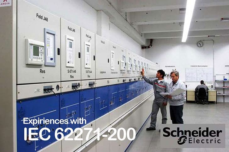
Expiriences with IEC 62271-200 in case of internal arc testing
The current valid international standard for metal-enclosed switchgear and controlgear for rated voltages from 1 kV and up to and including 52 kV is written in the first edition IEC 62271-200 from November 2003.
The current standard is the result of the revision of IEC 60298 from December 1990 [3]. In 2006, the second edition of IEC 62271-200 was prepared by subcommittee SC17C and the project was assigned to maintenance team 14. The target date for the committee draft (CD) is proposed for June 2007, which will be followed one year later by committee draft for voting (CDV) in June 2008. The final draft international standard (FDIS) is foreseen in June 2009 and the date of publication as an international standard will be in December 2009.
The major change of IEC 62271-200, edition 1.0, is the revision of new definitions and classifications of equipment of metal-enclosed switchgear and controlgear. Other main modification are the introduction of internal arc classes (IAC) and the description of methods for testing. The qualification of a new design of a metal-enclosed switchgear and controlgear is done by several type tests.
The personal protection due to an internal fault in medium voltage metal-enclosed switchgear became in IEC 62271-200 a significant higher importance.
The internal arc class makes allowance for internal overpressure acting on covers, doors, etc., and it also takes into consideration the thermal effects of arc or it roots on the enclosure and of ejected hot gases and glowing particles.
The test arrangement shall include fully equipped test objects. Mock-ups of internal components are permitted with the same volume and external material as the original items and with no influence on the main and earthing circuit. The test shall be performed in every compartment of the switchgear and controlgear containing main circuits. Extensible modular units shall be tested in all compartments at the end of a minimum arrangement of two units. All the tests shall be done on representative functional units. In the case of fluid-filled compartments, other than SF6 (sulphur hexafluoride), the test shall be made with the original fluid at its rated filling conditions.
[pullquote_left]The replacement of SF6 with air is permitted, but the pressure rise will be different.[/pullquote_left] The pressure will rise more rapidly in air, because of the difference heat capacities. Experimental results show that the maximum overpressure in air is always higher than in sulphur hexafluoride at same test conditions. For example, tests of a compartment with a gas volume of ca. 0,08 m and a current of 31.5 kA showed an increase of the maximum pressure by 24 %. Therefore the mechanical stress of the metal-enclosed switchgear is for internal arc test in air higher than in SF6 and guarantees maximum protection with respect to rupture and deformation of the tested compartment. The room simulation and the arrangement of the test object are clearly defined; the room shall be represented by a floor, a ceiling, and two walls perpendicular to each other. The minimum distance between the ceiling and the upper part of the switchgear and controlgear shall be 600 mm ±100 mm. Respectively the minimum height of the ceiling shall be 2000 mm from the floor for test objects with a height of less than 1500 mm.
For lower clearances to the ceiling, the manufacturer may carry out an additional test. In many cases, switchgear buildings or substations in utilities or industries are optimised also to minimum dimensions with respect to costs.
Some users require very small building heights of less than 2500 mm, e.g. walkable compact substations and container. The standardised distance of 600 mm between the ceiling and the upper part of the switchgear, however, does not meet the technical requirements of the national and international market; a modification of this specification may be reasonable.
The lateral wall shall be placed at 100 mm ± 30 mm from the lateral side of the test specimen. The manufacturer may carry out an additional test with higher clearances to the lateral wall, in order to assess the criteria for installation conditions. From the technical view, testing with a minimum distance of 100 mm fulfills the criteria.
The definition of the rear wall depends on the type of accessibility. The employment of exhaust ducts to guide generated hot gases during the internal arc test, shall be tested with the minimum cross-section dimensions, location and output features of the ducts, like flaps or grid. The output end of the exhausting ducts shall be al least 2000 mm away from the tested switchgear and controlgear.
The material, fixation, and arrangement of the indicators are defined in detail to assess the thermal effect of thengases. The indicators shall be placed on a mounting rack at each accessible side at distances depending on the type of accessibility.
To simulate the position and work clothes of authorised operators (accessibility type A) the distance of indicators to switchgear and controlgear shall be 300 mm ± 15 mm. Indicators shall be fitted vertically at all accessible sides up to a height of 2000 mm, arranged in a checkerboard pattern so that 40 – 50 % of the area is covered.
The horizontal indicators shall be arranged to a height of 2000 mm above the floor and covering the whole area between 300 mm and 800 mm from the test object; when the ceiling is placed at a height of 2000 mm above the floor, no horizontal indicators are necessary. The arrangement of the horizontal indicators shall be in the same way as the vertical ones. The arrangement of accessibility type B shall be assessed against the consequence of an internal arc fault for the general public.
The main difference between accessibility type A and B is the reduction of the distance between the vertical and horizontal indicators and the enclosure to 100 mm ± 5 mm. The horizontal indicators shall be arranged to a height of 2000 mm above the floor and covering the whole area between 100 mm and 800 mm from the metal-enclosed switchgear and controlgear. If the height of the test object is lower than 2000 mm, vertical and horizontal indicators shall be placed at a distance of 100 mm ± 5 mm higher respectively direct on the top cover.
The internal arc test shall be carried out three-phase for three-phase systems. The short-circuit current applied during the test corresponds to the rated short-time withstand current. It may be lower if specified by the manufacturer. The value of the peak current shall be 2.5 times of the rated current for frequencies up to 50 Hz and 2.6 times for frequencies up to 60 Hz.
The manufacturer shall define the duration of the test. Standard recommended values are 1 s, 0.5 s and 0.1 s. The energy feeding direction is described in detail for each compartment of the switchgear and controlgear. The arc initiation shall be done between all three phases or between one phase and earth of segregated phase conductors. The point of initiation in the compartment shall be located at the furthest accessible point from the supply, within the compartment under test. In case of segregated phase conductors, the arc ignition shall be between one phase and earth at gaps or joining surfaces between the insulation of insulation-embedded parts.
The initiation of the arc in a cable compartment shall be done between two phases at the plugs without insulation and the third phase shall be provided with a plug-in connector as can be used in service and able to be energised.
- Class IAC AFLR
- Internal arc: 40 kA 1 s
The example describes a qualified metal-enclosed switchgear and controlgear according to the IAC class. The accessibility type is A for authorised personnel only on the front, lateral and rear side; the short-circuit current is 40 kA and the test duration is 1 s. The defined internal arc test does not consider all effects of an internal fault. For example the dynamic mechanical stress on the walls of the switchgear room or building due to the overpressure is not considered.
The standard does not provide rules how to calculate the effect of the overpressure when the hot gases will rupture over pressure relief devices inside the switchgear room or building. It is only written, that it should be taken into consideration when designing the installation.
The IEC62271-200 enforces high requirements for the design of metal-enclosed medium voltage switchgear and controlgear. The end user of such qualified switchgear and controlgear can be sure that the protection against an internal fault for the operator and for the general public is very high.
AUTHORS
REFERENCES
[1] IEC 62271-200, first edition, 2003-11, “AC metal-enclosed switchgear and controlgear for rated voltages above 1 kV and up to and including 52 kV”
[2] IEC 60298, edition 3.0, 12/1990, “AC metal-enclosed switchgear and controlgear for rated voltages above 1 kV and up to and including 52 kV”
[3] A. Wahle, S. Ruhland, 2003, “Influence of the new IEC 60298 with respect to the design of metal-enclosed medium voltage switchgear”, Session 1, CIRED 17 th International conference on electricity distribution, Barcelona, Spain
[4] www.areva.com
Related electrical guides & articles


Edvard Csanyi
Hi, I'm an electrical engineer, programmer and founder of EEP - Electrical Engineering Portal. I worked twelve years at Schneider Electric in the position of technical support for low- and medium-voltage projects and the design of busbar trunking systems.I'm highly specialized in the design of LV/MV switchgear and low-voltage, high-power busbar trunking (<6300A) in substations, commercial buildings and industry facilities. I'm also a professional in AutoCAD programming.
Profile: Edvard Csanyi

We want to conduct Arc flash test on our 11 kv CSS Enclosure Is it possible to get a design so that the test can be with stand
Dear Sir,
As regarding internal arc I have few questions
1. Is it mandatory that iternal arc test should be conducted in 11Kv and above swgrs.
2. if it is yes , can we do it in main bus bar and cable chamber only , as the breakers are type tested by OEM, do we need to test them again.
In case of 415 volt system paritcularly the MCC and Power distribution board will typically contain 5-6 modules in each vertical ,how to do arc test for them .
Kindly advise
with best regards
suresh
What is the logic behind selection of Internal Arc duration.
0.1,0.2,0.3,0.5,1 Sec etc…
Dear Sir
Is it true If a Switchgear Unit is capable to clear IAC within 0.1 sec i,e opened Gas Flap it will clear 1 sec ? If not, why?
How to consider the duration of arc fault test? It is because the worst case is the operation of back up protection to clear the fault. In that case, the duration of fault would be longer. I understand 1 second is the standard of IEC but please advise any risk assessment was conducted to determine this 1 second. Otherwise, how do we consider the risk assessment?
What affect does cable installation have on the arc fault capability of switchgear, for example an AFLR rated RMU with venting to a rear chimney, but if its 11kv cables come up from a cable pit the arc flash will vent into the pit as well as up the chimney and create a hazard for maintenance staff.