Continued from: Internal arc testing of MV switchgear – IEC 62271-200 (part two)
Development of a new GIS generation according to IEC 62271-200 with respect to internal arc type tests
The following chapter describes the development of a new gas-insulated switchgear generation GHA [4] for primary distribution for internal arc testing according to IEC 62271-200.
All tests were successful passed for internal arc class IAC AFL / AFLR and a short-circuit current up to 40 kA (104 kA peak) with a test duration of 1 s. The metal-enclosed gas insulated switchgear GHA is performed in a compact modular design with the possibility of extensibility on both sides. The rated voltage is up to 40.5 kV and a rated current up to 2500 A; the busbar system is available in single (SBB) and double busbar (DBB).
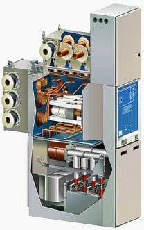
Fig. 1 presents the switchgear and controlgear GHA with circuit breaker (vacuum interrupter), outer coin cable connection and double busbar.
The spatial and temporal distributions of pressure and temperature and fluid velocities, that result from an internal arc fault, are determining parameters for many aspects in the mechanical design. For that reason, various 3-D simulations of the arc test conditions were performed in the development process of the new AREVA product GHA.
Simulations and type tests were performed for a three-phase ignition with the rated short circuit current in the busbar compartment (iBB) and inside the circuit breaker compartment (iCB), and a two-phase ignition with 87 % of the rated current between two adjacent phases at the cables in the cable compartment (iCC).
Here, simulation results for the iCC configuration are presented and are compared to the test measurement results. When an internal arcing fault occurs, a lighting plasma arc forms a short circuit and an energy of many MJ is released within a second of time.
Most of that energy is transferred to the insulation fluid, which is air in the case presented here. The air in the arc region is thereby heated up to temperatures of several thousand Kelvin within some milliseconds of time, causing the gas to expand explosively emitting a pressure wave. At these high temperatures, part of the energy is consumed by dissociation and ionisation of the gas molecules; another part of it is emitted as thermal radiation, heating the surrounding material.
Progressing in time, an increasing part of the energy is consumed by heating and melting and evaporation of electrode and cladding material, known as the thermal phase.
Modern simulation tools basically allow to predict the effects caused by an internal arc. The finite element (FE) method is a suitable tool to address that issue, for it provides the required spatial and temporal resolution. In FE analysis, the fluid volumes of a switchgear or controlgear system are first divided into a mesh of finite volumes, for which then the coupled Navier-Stokes equations are solved by means of a computational fluid dynamics (CFD) code.
For the GHA, three-dimensional FE-models were set up with a simplified arc model implied. The model geometry for iCC is shown in Fig. 2.
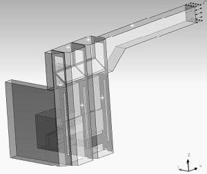
The model resembled a system of two GHA single busbar functional units with a pressure relief channel. The geometry consisted of the volumes of the cable compartment and the pressure relief channel. The opening of the channel is at the far end of the 2000 mm length exhaust duct, where hot gases are released to the ambience outside a container. Cross symbols indicate the pressure measurement points.
The maximum peak value and the rise time of fluid pressure as well as it’s spatial distribution are of major interest for the design with respect to the stress on the switchgear and the channel. This peak value usually is reached within the first 20 to 30 ms after ignition, or after opening of a pressure relief device, in systems consisting of two functional units. When focussing to the first milliseconds, effects in the subsequent thermal phase of the internal arc fault can be neglected in first approximation.
An electric arc, which is initiated between the cables with feeding from the bus bar, will move to the furthest distant end of conductors from the power supply. There, it expands into the air volume of the cable compartment, driven by magnetic forces. The magnetic, electric and thermal forces keep the arc moving. In simulation, the lighting arc was modelled as a volume heat source, that was applied to a small volume fraction of the cable compartment. This volume fraction resembled an estimate of the volume, into which the electric arc most likely will expand to. Since the focus was on the first milliseconds after ignition and since radiation losses as well as a temperature dependent specific heat capacity was considered, there was no need to define a power transfer coefficient, as usually introduced in such calculations.
The electric power supplied to the arc was calculated from the short circuit current as a function of time and a constant voltage. Fig.3 shows the calculated electric power together with the measured arcing power for iCC. The short-circuit current was 34.8 kA (87 % of 40 kA), in accordance with IEC specification.

Fig. 4 shows the measured pressure together with the calculated pressure rise at the front door of the cable compartment. Soon after ignition of the electric arc, there is a steep increase of pressure in the cable compartment.
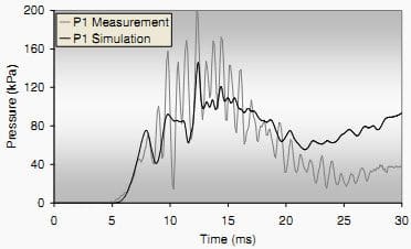
The first peak in this increase is due to the direct incident pressure wave at the measurement point. While overall pressure still increases by heating of the gas, oscillations show up in the pressure curve.
These oscillations come from reflections of the pressure wave. The calculation reproduced the measurement results well over the first milliseconds. Since some power losses were neglected, the pressure rise after the first 20 ms is overestimated. Reflections of the pressure wave are not fully resolved in the simulation, due to geometric simplifications of the cable compartment geometry and the interior components.
With increasing distance from the source, the peaks in the pressure course become less pronounced, because of damping and superposition of pressure waves.
Fig. 5 shows the pressure at the top of the channel of the tested unit.
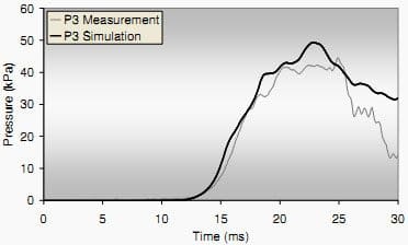
The design of the channel modules provided openings interconnecting the modules and also to a channel volume at the lateral side walls of the system. This allowed for attenuated expansion of the pressure wave throughout the channel system while reducing pressure load at the origin unit.
Fig. 6 presents the pressure at the tapering of the exhaust duct.
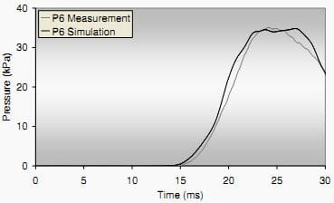
Simulations were carried out in the development stage and had a major impact on the design. Resulting pressure levels, for example, determined the design of the front door of the cable compartment and of the joints of the channel system, as well as of the interconnection openings.
Analysis of the temperature distribution and fluid velocity helped to decide on need for thermal shielding. Eventually, combining experience with modern simulation tools allowed for successful testing according to IEC 62271-200, wile reducing the need for cost intensive test cycles. SUMMARY Experiences with IEC 62271-200 in case of internal arc testing of medium voltage switchgear were presented.
The comparison of individual requirements of national and international users, utilities and industries, and the definitions of the IEC-standard for internal arc test were discussed.
The need for modern simulation methods in the development of a new product was stressed, in order to comply with the stringent requirements of the new standard. Simulation and type test results for one of the internal arc tests according to the standard were presented and compared.
AUTHORS
REFERENCES
[1] IEC 62271-200, first edition, 2003-11, “AC metal-enclosed switchgear and controlgear for rated voltages above 1 kV and up to and including 52 kV”
[2] IEC 60298, edition 3.0, 12/1990, “AC metal-enclosed switchgear and controlgear for rated voltages above 1 kV and up to and including 52 kV”
[3] A. Wahle, S. Ruhland, 2003, “Influence of the new IEC 60298 with respect to the design of metal-enclosed medium voltage switchgear”, Session 1, CIRED 17 th International conference on electricity distribution, Barcelona, Spain
[4] www.areva.com




we are doing servicing of mv air insulated vcb during servicing facing lot of insulation failure of resin cast components. we want alternate better material at cheaper cost