
Estimated Study Time: 10 minutes
Progression of internal faults
Transformers are subjected to many external electrical stresses from both upstream and downstream that can lead directly to internal fault(s). The consequences of any failure can be very great in terms of damage as well as in terms of operating losses.
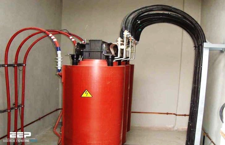 Why and where do internal faults happen in substation transformers (on photo: 630KVA Dry-type 20/0.4kV distribution transformer; credit: vakfaris.eu)
This article explains three major internal fault types that can occur in MV/LV substation transformers.
- Faults between turns
- Faults between windings
- Faults to earth and the influence of the neutral earthing arrangement
1. Faults between turns
Faults between medium voltage winding turns are the most frequent failure mode as well as being the most difficult to detect.
They result from the localized deterioration of conductor insulation, due to thermal or dielectric stresses. The initial effect is limited to a slight increase in the primary current, due to the modification of the transformation ratio on the one hand and the appearance of a short-circuited turn phenomena on the winding concerned.
This faulty turn behaves as a secondary winding and is the seat of a current limited solely by its own impedance and the resistance at the point of fault (see figure 1).
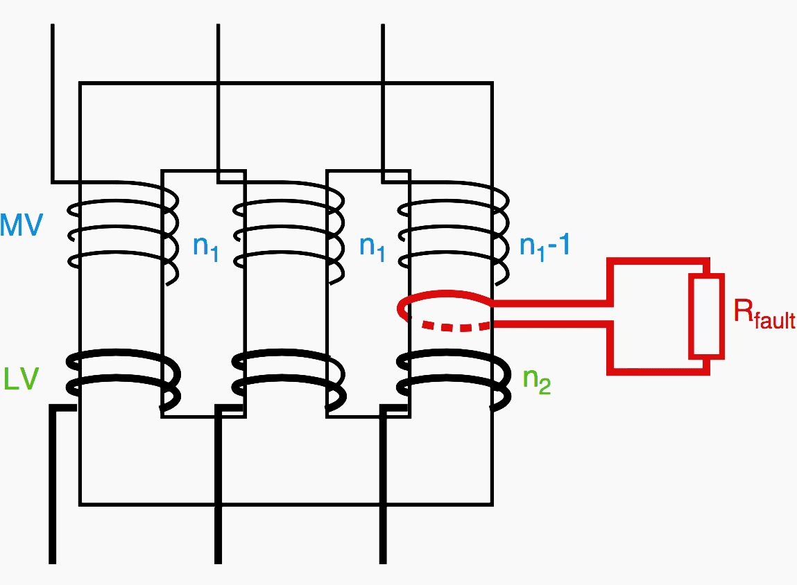
According to the current that passes through this turn, the progression of the fault will be more or less rapid. In the case of high currents, the local temperature rise will lead to the deterioration of the neighboring turns and the fault will quickly spread.
The order of magnitude corresponds to approximately one hundred times the rated current or around 1 kA for the primary winding of a transformer of 400 kVA under 20 kV!
If the fault causes a low primary current, the phenomena can be slow and difficult to detect through monitoring of the supply current. Laboratory tests on oil filled transformers have shown current of between 1 and 6 times the rated current, accompanied by large gaseous release, for faults involving up to 8 % of the primary turns.
This is why monitoring of gaseous emissions or pressure can be used in a complementary manner to protection devices based on current measurement.
2. Faults between windings
MV windings
Faults between MV windings are rare but can cause high fault currents, up to the network short circuit current in the case of a fault at the terminals, with significant effects.
Certain locations in particular, such as a fault between windings neighboring neutral point connections of a star coupling, are similar to a fault between turns since the points coming into contact are not at greatly differing voltages.
LV windings
Faults between LV windings are exceptional since these windings are placed closest to the magnetic core and are surrounded by the MV windings. In the case of multiple LV windings on the same magnetic core column (e.g. zig-zag coupling), the possibility of a fault exists.
In any case, the fault current remains less than that of a short circuit across the secondary terminals, but progression can be quick due to the presence of an arc of significant intensity.
MV/LV
A fault between windings can also lead to a contact between the primary and secondary, with the appearance of a dangerous potential on the low voltage network. The risk to equipment and people depends on the neutral arrangement of the two networks (see figure 2).

In certain applications, for enhanced safety of the lowest voltage winding, the use of a shield connected to earth, positioned between the primary and secondary windings enables this fault hypothesis to be eliminated by favoring phase-earth faults.
3. Faults to earth and the influence of the neutral earthing arrangement
Faults between MV windings and earth most frequently originate from a break in insulation following an overvoltage. Nevertheless they can also be the result of mechanical type faults or the progression of an electrical fault as previously seen.
The characteristics of an earthing fault, as well as the capacity to detect it, depend on the supply network earthing arrangement and on the location of the fault in the transformer (see figure 3).

Case of a non-distributed medium voltage neutral
In the case of a non-distributed medium voltage neutral, connected to earth by an impedance of some sort, the fault will cause a current to earth to appear varying as a function of the neutral impedance and the position of the fault on the winding. In the case of a very low fault current, there is a risk of a slow increase in pressure similar to that for faults between the turns.
Arbitrarily fine detection of the current to earth would be an effective means of protection. Nevertheless, such protection is not always technically and/or economically achievable.
Case of a tuned neutral network
In the case of a tuned neutral network (earthed by a Petersen coil), an insulation fault in an oil filled transformer will be of recurring self-extinguishing type. The low value of the fault current enables its spontaneous extinction in the oil and progressive reappearance of the voltage, characteristic of a tuned neutral network, leading to another breakdown several hundreds of milliseconds later.
The frequency of the phenomena will increase if there is progressive deterioration by successive breakdowns leading to a lowering of the dielectric withstand.
Case of a neutral network directly connected to the earth and distributed
In the case of a neutral network directly connected to the earth and distributed (4 wires network, of North American type), the presence of neutral current is normal, due to the existence of single-phase loads, and the appearance of a fault will increase this current (as a function of the impedance of the winding section not in short circuit).
A significant proportion of faults concern the transformer’s frame, then the ground Protection against earth faults is therefore useful.
The current to earth being zero under normal conditions (except in networks with an earthed and distributed neutral arrangement), such protection can be set with a low threshold, e.g. 10 % of the rated current with a time delay of 100 ms, in cases with current transformers and a few amperes in cases using a residual current sensor.
Reference // Protection of MV/LV substation transformers by D. Fulchiron (Schneider Electric)
Related electrical guides & articles


Edvard Csanyi
Hi, I'm an electrical engineer, programmer and founder of EEP - Electrical Engineering Portal. I worked twelve years at Schneider Electric in the position of technical support for low- and medium-voltage projects and the design of busbar trunking systems.I'm highly specialized in the design of LV/MV switchgear and low-voltage, high-power busbar trunking (<6300A) in substations, commercial buildings and industry facilities. I'm also a professional in AutoCAD programming.
Profile: Edvard Csanyi

Good analysis of medium voltage transformer fault . Dielectric strength , sludge formation in oil cooled transformer , silica gel , earting also play important role in development of fault in oil cooled transformer
Hi Edvard
I wonder if you can refer me to an engineer with good HV GIS expertise for a 2-3 month assignment in Senegal for a substation commissioning job … must have good French language skills.
Will appreciate your assistance.