It’s all bout loads and ratings
A complex project comprises loads ranging from small loads such as sockets and lights to higher loads like Air Handling Units (AHUs), Fan Coil Units (FCUs), motor pumps, and other high motor-driven loads. Loads connected to the project are gathered and represented with symbols in what is known as a “single-line diagram.”

Single-line diagram is considered vital for maintenance activities, tracking the location of faults, and useful for operators to identify the electrical placement of different devices and components. In an LV distribution system, the diagram should clearly show the main, sub-main, and distribution panel boards and the motor-driven loads of the project represented with symbols.
These loads are connected by cables or busbars which must be clearly shown in the single-line diagram. Also, a single-line diagram represents comprehensive data for each component or device connected to it.
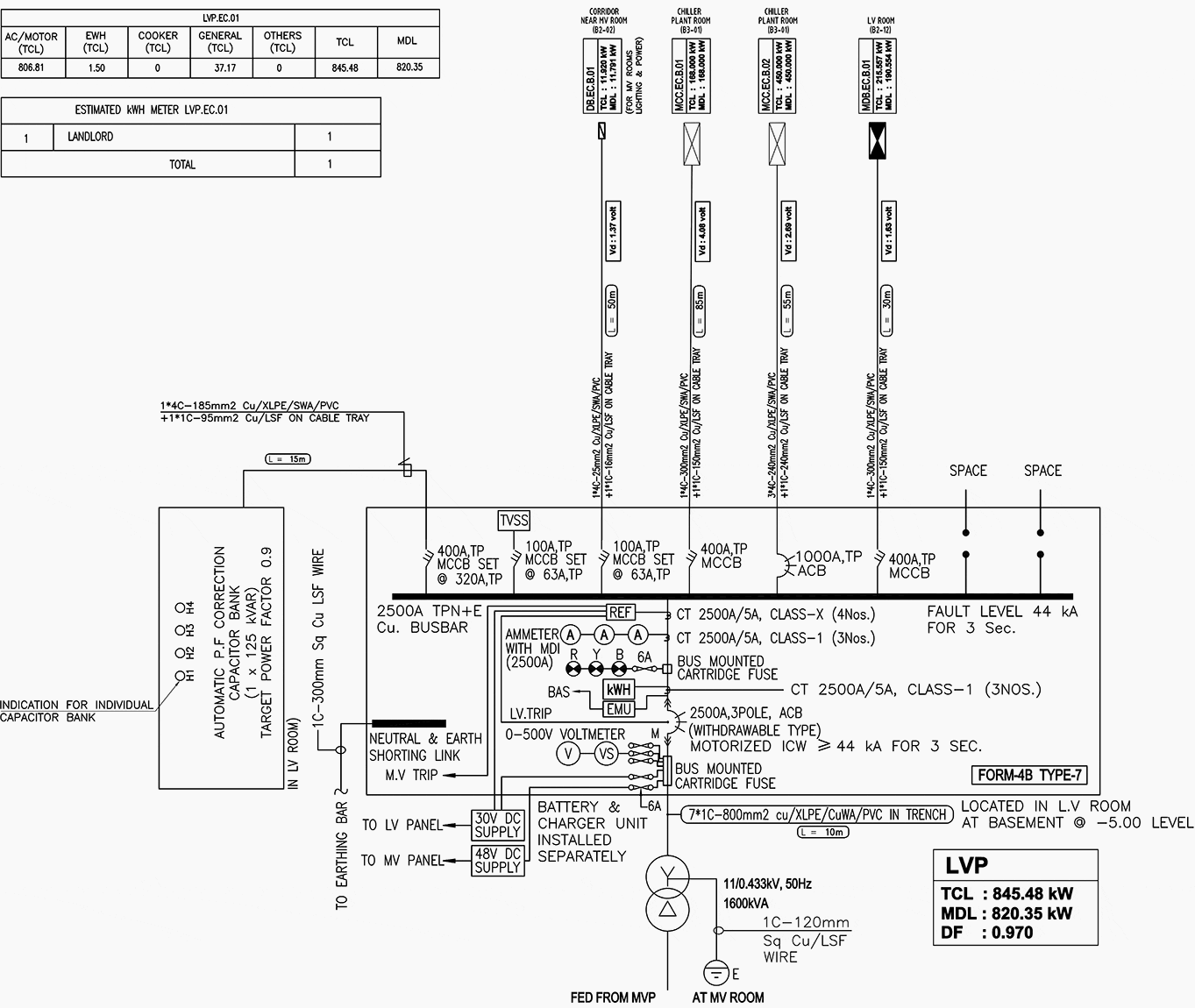
In other words, the exact cable sizes, circuit breakers ratings, voltage drop values, and short circuit current calculated values must be reflected in the low voltage distribution single line diagram. The diagram must show the source of supply power to the project, either the generator or the step-down transformer at the start, down to the final distribution board or final connected load.
Every component included in the SLD will be explained, and clarify why it is mentioned in the diagram and why it is functional. Moreover, the design of an SLD will be explained using the well-known AutoCAD drafting software.
- HV to LV Generation, Transmission & Distribution of Power
- Interpreting a LV Panel Single-Line Diagram
- Interpreting a SLD with a Backup Generator
- Sub-main Panel SMDB Single Line Diagram
- MCC Panel Single Line Diagram
- Design a Single Line Diagram in AutoCAD
1. HV/LV Generation, Power Transmission & Distribution of Power
To understand the low voltage side of power distribution in a single-line diagram, let’s remind ourselves how electric power is delivered to our homes and other facilities. Electricity passes through three stages: generation, transmission, and distribution.
Electricity is generated in power plants or power stations with a voltage of 11KV, then stepped up using step-up transformers to increase the voltage to between 100 KV to 700KV depending on the distance it will be transferred to; the longer the distance, the higher the voltage. After that, electricity is transmitted via overhead electrical lines, which we can notice when driving between cities.
When electrical power reaches a substation, it is stepped down once more by a step-down transformer to voltages closer to what was generated at usually around 11kV. From here, the transmission phase graduates to the distribution phase, and electrical power is used to meet demand from primary and secondary consumers.
Figure 1 – Low Voltage Panel Single Line Diagram


This is done by installing a low-voltage transformer that steps this voltage down to 500V or less for distribution. So, to understand a LV single-line diagram, it is advised to know how power is generated, transmitted before studying the distribution part which is what will be covered in this article.
In this article, our main aim is to understand the distribution part of the single-line diagram, which does not include the upstream side of the transformer. In other words, the SLD shall not represent what is before the low-voltage transformer and will only show the connections from the LV transformer to distribution boards and other end branch loads.
Figure 2 – Generation, Transmission and Distribution SLD of Power System


Go back to the Contents Table ↑
2. Interpreting a LV Panel Single-Line Diagram
A single-line diagram (SLD) or a one-line diagram (OLD) is a simplified schematic representing a three-phase system’s electrical elements with a single line representing the connected conductors. We can say that the single-line diagram is finished once all loads are distributed throughout the project in the last stages.
The design of a single diagram is relatively easy. However, the electrical designer must understand how to interpret a single-line diagram to perform a well-designed SLD adequately.
Of course, the symbol must also include written text showing the transformer specifications, like its rating and type. Right after the transformer, the main distribution board, or what is known as the LV panel, should be reflected in the diagram. The LV panel is considered the main panel that feeds the entire project.
Suggested Course – Learn AC Distribution Panel Drawings: SLDs, Wirings & Interlocking Schematics
Learn AC Distribution Panel Drawings: Single-Line Diagrams, Wirings, and Interlocking Schematics
Low voltage panel comprises the main circuit breaker, indicating lamps, ammeters, fuses, outgoing circuit breakers, and other related components that should be represented in the diagram with symbols, including their specifications and types.
The main LV panel must feed several sub-main panels connected by conductors, cables, or busbars. The conductors connected between the LV and sub-main panels must be represented by one line regardless of the number of conductors connected. This explains why it is called a single-line diagram.
Premium Membership Required
This technical article/guide requires a Premium Membership. You can choose an annually based Plus, Pro, or Enterprise membership plan. Subscribe and enjoy studying specialized technical articles, online video courses, electrical engineering guides, and papers. With EEP’s premium membership, you get additional essence that enhances your knowledge and experience in low- medium- and high-voltage engineering fields.
Check out each plan’s benefits and choose the membership plan that works best for you or your organization.


