
Estimated Study Time: 28 minutes
Operating 132kV GIS Transformer Bay & Line Bay
This article aims to provide a comprehensive guide to the standard operating procedures (SOPs) for the isolation, maintenance, and restoration of a 132kV GIS Transformer Bay and Line Bay. It will delve into detailed safety checks, specific steps to be followed during the isolation process, and the restoration protocols to be adhered to post-maintenance.
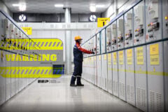
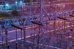
 How to: Isolation, maintenance, and restoration of a 132kV GIS Transformer Bay and Line Bay (on photo: Blackhill Substation, Scotland, credit: Kirby Group)
Additionally, the article will cover the procedures for handling transformer oil sampling, a critical aspect of maintaining transformer health and performance.
As yo already know, high Voltage (HV) substations are critical components of the electrical grid, playing a pivotal role in ensuring the reliability and stability of power transmission and distribution. Among these, the 132kV Gas Insulated Switchgear (GIS) substations are particularly significant due to their compact design, enhanced safety features, and superior operational efficiency.
By systematically outlining these procedures, this article seeks to serve as a valuable resource for electrical engineers, maintenance personnel, and safety officers involved in the operation and upkeep of 132kV GIS substations.
The meticulous application of these SOPs not only enhances operational efficiency but also significantly mitigates the risks associated with high-voltage electrical systems.
- Standard Operating Procedure for Isolation and Maintenance of a 132kV GIS Transformer Bay:
- SoP for 132kV Power Transformer Trip & Restoration:
- SoP for 132kV Line Trip & Restoration:
- SOP for Transformer Oil Sampling:
- BONUS (PDF) 🔗 Download 132kV GIS Drawings of HV Devices and LCC + Design & Execution Guide (PDF)
1. Standard Operating Procedure For
Isolation and Maintenance of a 132kV GIS Transformer Bay
The primary aim of this procedure is to provide a comprehensive guide for the operation, isolation, and restoration of the 132kV transformer bay within a high-voltage (HV) substation.
This procedure outlines the specific steps required to isolate and restore the 132kV transformer bay, ensuring that all activities are conducted safely and effectively. Isolation is necessary for performing maintenance, repairs, or upgrades, and it involves de-energizing and securing the transformer bay to protect personnel and equipment.
This procedure aims to minimize downtime, prevent accidents, and maintain the reliability and stability of the electrical supply.
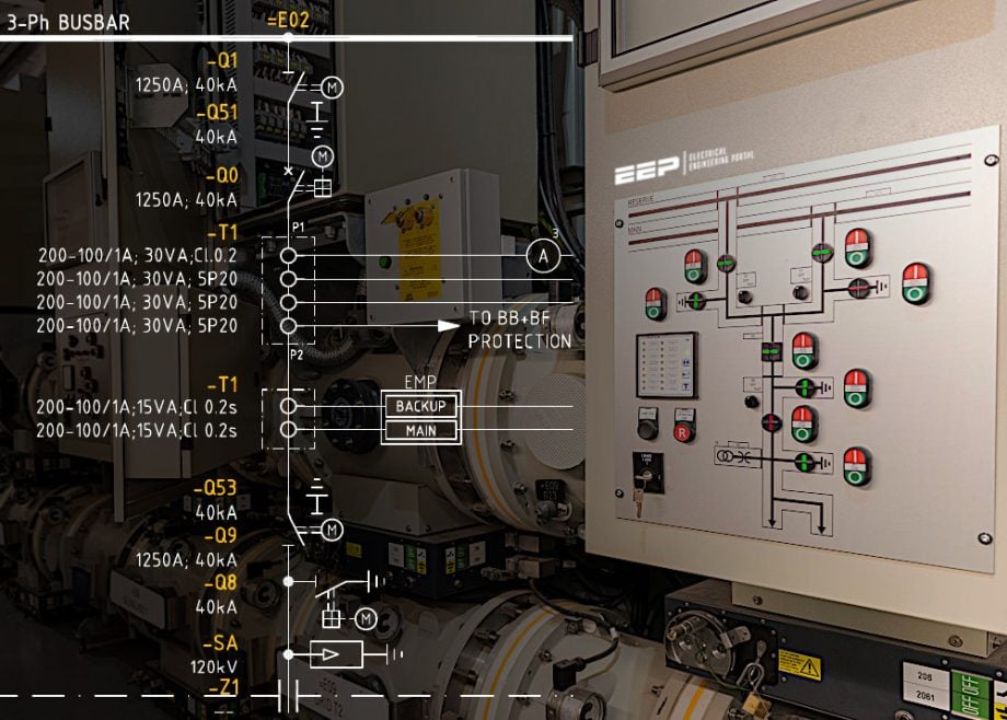
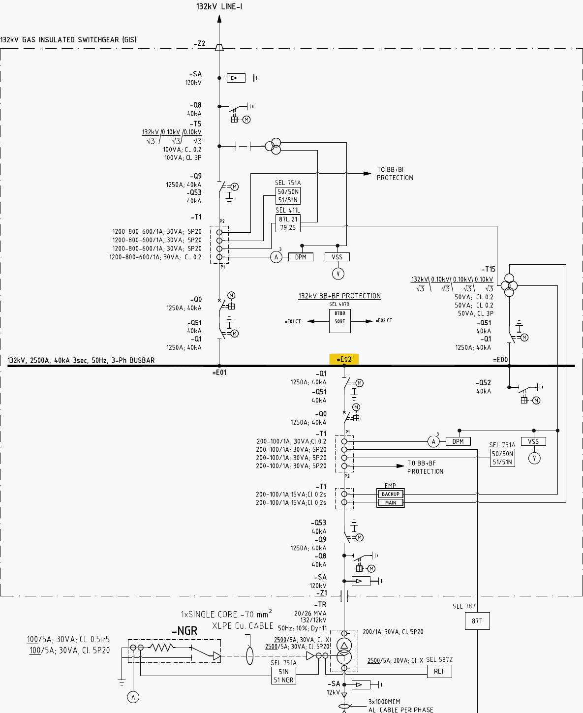
Figure 1 – Single Line Diagram for the 132kV Transformer Bay at Substation
1.1 Isolation Procedure
Step No.1 – Open the E02 Q0 Transformer Bay Circuit Breaker:
- Navigate to the control panel corresponding to the E02 Q0 Transformer Bay.
- Locate the circuit breaker control switch and set it to the “Open” position.
- Verify that the circuit breaker has successfully opened by checking the indicator lights on the control panel.
Step No.2 – Open the E02 Q1 Bus Isolator:
- Identify the E02 Q1 Bus Isolator, which disconnects the busbar from the transformer bay.
- Operate the control mechanism to move the isolator to the “Open” position.
- Confirm that the bus isolator is fully open, ensuring there is no physical connection between the busbar and the transformer.
Step No.3 – Open the E02 Q9 Line Isolator:
- Locate the E02 Q9 Line Isolator, which isolates the transmission line from the transformer bay.
- Actuate the isolator to the “Open” position using the control handle or switch.
- Check the status indicators to verify that the line isolator is completely open.
Step No.4 – Close the E02 Q51, E02 Q53, and E02 Q8 Earthing Switches:
- Identify the earthing switches E02 Q51, E02 Q53, and E02 Q8, which ground the disconnected equipment for safety.
- Operate each earthing switch to the “Close” position.
- Ensure that each earthing switch is securely closed, and that the equipment is properly earthed, providing a safe work environment for maintenance personnel.
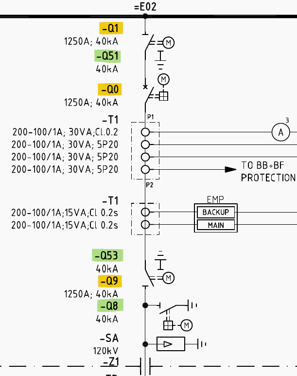
Figure 2 – Isolation of 132kV GIS Transformer Bay
1.2 Checking for Live Parts
Step No.1 – Verify De-energization with a Live Line Tester:
- Use a live line tester to check that no part of the MV bushing and busbar is live.
- Perform the test on the MV bushing first, ensuring no voltage is present.
- Repeat the test on the busbar, confirming complete de-energization.
- Record the test results and proceed only if both tests confirm that the equipment is de-energized.
Related electrical guides & articles


Muhammad Kashif
Muhammad Kashif Shamshad is an Electrical Engineer and has more than 17 years of experience in operation & maintenance, erection, testing project management, consultancy, supervision, and commissioning of Power Plant, GIS, and AIS high voltage substations ranging up to 500 kV HVAC & ±660kV HVDC more than ten years experience is with Siemens Saudi Arabia.Profile: Muhammad Kashif
