Transformer noise signals
Transformers are not perfect. Transients and noise (radio-frequency and low-level spikes) normally pass through transformers, not only by way of the magnetic lines of flux between the primary and the secondary windings but through resistive and capacitive paths between the windings, as well.

There are two basic types of noise signals with which transformer designers must cope:
- Common-mode noise: Unwanted signals in the form of voltages appearing between the local ground reference and each of the power conductors, including neutral and the equipment ground.
- Normal-mode noise: Unwanted signals in the form of voltages appearing in line-to-line and line-to-neutral signals.
So, what can be done us suppress this noise? Well, increasing the physical separation of the primary and secondary windings will do the magic and reduce the resistive and capacitive coupling. However, it also will reduce the inductive coupling and decrease power transfer.
One application of this technology is shown in Figure 1, in which transformer noise decoupling is taken a step further by placing the primary and secondary windings in their own wrapped foil box shields.
Figure 1 – The shielding arrangement used in a high-performance isolation transformer
The design goal of this mechanical design is high common-mode and normal-mode noise attenuation.


The windings are separated physically as much as possible for the particular power rating and are placed between Faraday shields. This gives the transformer high noise attenuation from the primary to the secondary, and from secondary to the primary. Figure 2 illustrates the mechanisms involved.
Capacitances between the windings, and between the windings and the frame, are broken into smaller capacitances and shunted to the ground, thus minimizing the overall coupling.
Figure 2 – The elements involved in a noise-suppression isolation transformer, where:
- Conventional transformer with capacitive coupling as shown;
- The addition of an electrostatic shield between the primary and the secondary;
- Transformer with electrostatic box shields surrounding the primary and secondary windings.
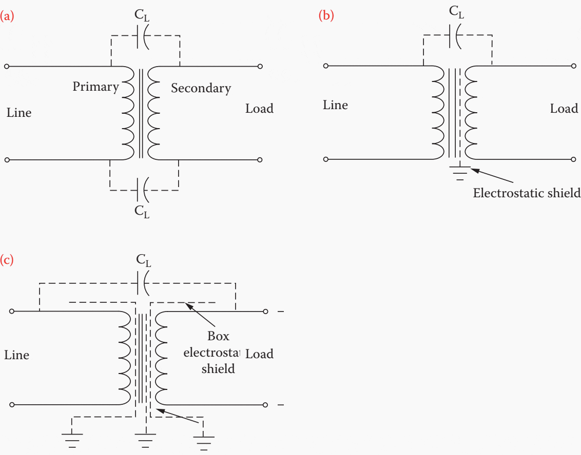

Figure 3 illustrates how an isolation transformer combines with the AC-to-DC power supply to prevent normal-mode noise impulses from affecting the load.
Figure 3 – How the normal-mode noise attenuation of an isolation transformer combines with the filtering characteristics of the AC-to-DC power supply to prevent noise propagation to the load.


A 5 kVA noise-suppression isolation transformer is shown in Figure 4. High-quality isolation transformers are available in sizes ranging from 125 VA single-phase to 125 kVA (or more) three-phase. Usually, the input winding is tapped at 2.5% intervals to provide the rated output voltage, despite high or low average input voltages.
The total tap adjustment range is typically from 5% above nominal to 10% below nominal. For three-phase devices, typical input-voltage nominal ratings are 600, 480, 240, and 208 V line-to-line for 15 kVA and larger.
Figure 4 – Topaz 5000VA Ultra-Isolation transformer


1. Tap-Changing Regulator
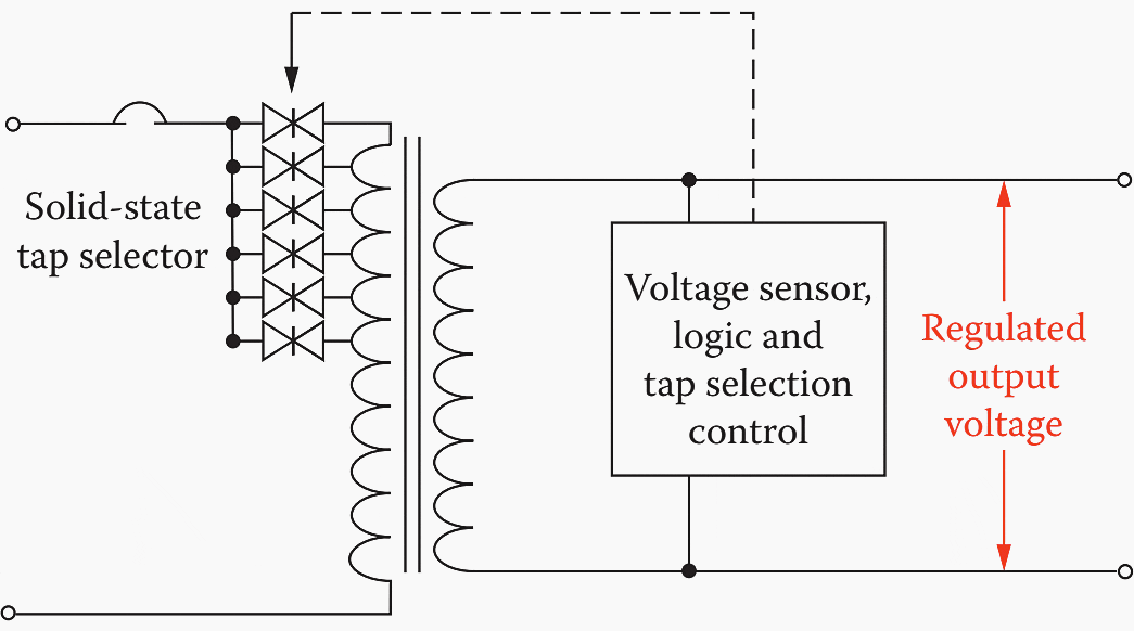
The concept behind a tap-changing regulator is simple: adjust the transformer input voltage to compensate for AC line-voltage variations. A tap-changing regulator is shown in Figure 5.
Although simple in concept, the actual implementation of the system can become complex because of the timing waveforms and pulses necessary to control the SCR banks. Because of the rapid response time of SCRs, voltage adjustment can be made on a cycle-by-cycle basis in response to changes in both the utility input and the load.
Tap steps are typically 2 to 3%. Such systems create no objectionable switching transients in unity power factor loads. For low-PF loads, however, small but observable transients can be generated in the output voltage at the moment the current is switched. This noise usually has no significant effect on distribution panel loads.
Figure 5 – Simplified schematic diagram of a tap-changing voltage regulator

Other operating characteristics include:
- Low-internal impedance (similar to an equivalent transformer)
- High efficiency from full load to 25% or less
- Rapid response time (typically one to three cycles) to changes in the input ac voltage or load current
- Low acoustic noise level
An autotransformer version of the tap-changing regulator is shown in Figure 6 below.
Figure 6 – Tap-changing voltage regulator using an autotransformer as the power-control element


1.1 Variable-Ratio Regulator
Functionally, the variable-ratio regulator is a modified version of the tap-changer. Rather than adjusting the output voltage in steps, the motor-driven regulator provides a continuously variable range of voltages.
The basic concept is shown in Figure 7.
The system is slow but generally reliable. It is excellent for keeping distribution panel hardware input voltages within the optimum operating range. Motor-driven regulators usually are able to follow the steady rise and fall of line voltages that typically are experienced on utility company lines. Efficiency is normally good, approaching that of a good transformer.
Figure 7 – Variable ratio voltage regulator
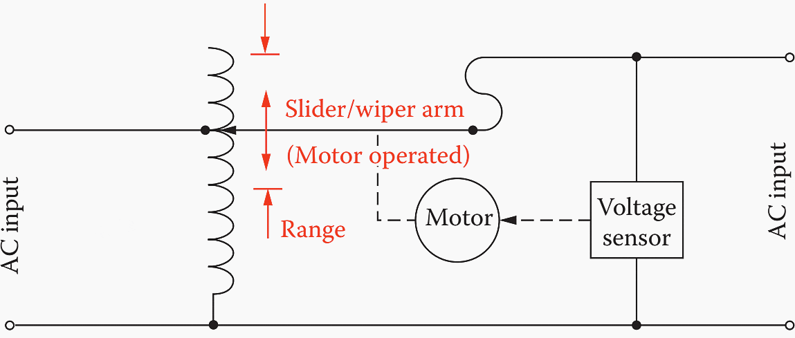

The internal impedance is low, making it possible to handle a sudden increase or decrease in load current without excessive undervoltages or overvoltages. Primary disadvantages of the variable ratio regulator are limited current ratings, determined by the moving brush assembly, and the need for periodic maintenance.
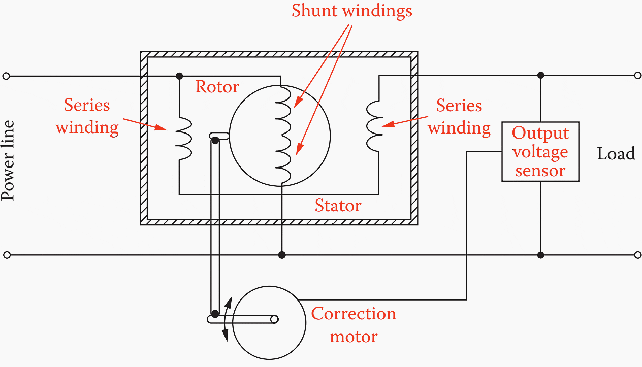
Variations on the basic design have been around, including the system illustrated in Figure 8 below.
A motor-driven brush moves across the exposed windings of an autotransformer, causing the series transformer to buck or boost voltage to the load. The correction motor is controlled by a voltage-sensing circuit at the output of the device.
Figure 8 – Motor-driven line-voltage regulator using an autotransformer with a buck/boost series transformer


The induction regulator, shown in Figure 9, is still another variation on the variable-ratio transformer. Rotation of the rotor in one direction or the other varies the magnetic coupling and raises or lowers the output voltage. Like the variable ratio transformer, the induction regulator is slow, but it has no brushes and requires little maintenance.
The induction regulator has higher inductive reactance and is slightly less efficient than the variable ratio transformer.
Figure 9 – Rotary induction voltage regulator

2. Variable Voltage Transformer
Because of their application in voltage control systems, it is worthwhile to discuss the operation of variable voltage transformers in greater detail. A number of conventional transformers can have — to a limited degree — their primary/secondary ratio changed through the use of taps located (usually) on the primary windings.
To obtain a greater degree of flexibility in changing the ratio between the primary and secondary coils, and thus allow greater secondary voltage changes, a variable voltage transformer is used.
The amount of voltage change depends upon the basic construction of the device, which typically divides into one of two categories:
- Brush type
- Induction type
2.1 Brush Type
To achieve a variable output voltage, one tap on the transformer secondary is fixed and the other tap is connected to a brush that slides along an uninsulated section of the transformer coil. One way of accomplishing this objective is to have the coil wrapped around a toroidal-shaped core.
The voltage ratio relates to the location of the brush as it rides against the coil and depends upon where on the coil the brush is allowed to make contact. Limited ratio variable transformers are available, as well as full-range units that can adjust the output voltage from 0 to about 120% of the incoming line voltage.
When the output voltage exceeds the input voltage, it means that there are extra turns on the coil that extend beyond the windings that lie between the incoming power terminals (in effect, the unit becomes a step-up transformer).
Sometimes, a control mechanism is attached to the rotor that turns the brushes, allowing automatic adjustment of the output voltage.
An important characteristic of this type of transformer relates to brush contact and the amount of current flowing through the carbon brush. A rating based solely on output kVA can cause serious operational problems because, for a given kVA load, the current drawn depends on the output voltage.
Because the output voltage is variable, a load of a given kVA value can draw a safe current at 100% voltage, but at 25% voltage, the current required to serve a load of the same kVA value would require four times as much current, which could cause the brush to overheat.
2.2 Induction Type
The induction type variable transformer does not use brushes. The usual voltage change for these units is ±10%, but it can be greater. The device is essentially a variable-ratio autotransformer that uses two separate windings, a primary and a secondary. There is a laminated steel stator on which is wound a winding that serves as a secondary coil. This winding is connected in series with the load.
The primary coil is connected across the supply line. The shunt winding is wound around a rotor. Construction is similar to that of a motor except that, in this case, the rotor can only turn 180 mechanical and electrical degrees.
Thus, the output voltage can be varied by adding or subtracting from it the voltage induced in the secondary winding. Both single- and three-phase transformers are available. Ratings of these types of transformers vary from 8 kVA, 120 V single-phase to 1500 kVA, 480 V three-phase.
Source: AC power systems by/ Jerry C. Whitaker




Good afternoon, clarification is required, What are the advantages of an AIR COOLED ULTRA ISOLATION TRANSFORMER over a OIL COOLING ULTRA ISOLATION TRANSFORMER
Regards-ANIL KUMAR G-HYDERABAD-INDIA
gracias por proporcionar conocimientos de vanguardia en este tema interesante para nosotros que no somos estudioso sino trabajadores de campo