Effects Of Moisture On Insulation
Deterioration Caused By Moisture
Special provision should be made to protect motor windings which operate in a damp atmosphere or are subject to condensation of moisture when out of service for long periods. Motors located in galleries of dams are frequently subject to continual moisture, either by dripping on the equipment or condensing on the cold metal parts.
Motors in irrigation pumping plants of either the indoor or outdoor type are generally shut down during the winter months and are subject to condensation of moisture, especially in localities where the atmospheric conditions are severe.
The moisture causes deterioration of the winding insulation and corrosion of the metal parts.
Absorption Of Moisture By Winding Insulation
Motor winding insulation, unless it is of the fully encapsulated thermosetting-resin type, readily absorbs water from the air. When any warm dry motor is shut down, it draws in fresh cool air, which always contains some moisture even in hot dry weather. After the motor has cooled, this moisture condenses within the porous winding insulation, as on the outside of a glass of ice water. On humid days or during rainy weather, the air contains much more than the normal amount of moisture and the insulation absorbs more.
Moisture is trapped in the insulation and requires heat and ventilation to drive it out. If the motor is operated continuously, or frequently, the insulation remains sufficiently dried out to prevent insulation failure. But if the motor stands idle for long periods, especially in unheated buildings during humid weather or in dam galleries, the trapped moisture may accumulate until the insulation becomes a partial conductor of electricity.
If normal voltage is then applied, the insulating material may fail. The insulation is thus ruined by the short circuit and the motor must then be rewound before it can be operated again. When rewinding, the new insulation should be given special impregnation, for humid climates, which is able to prevent moisture absorption.
Insulation Resistance
Measuring Insulation Resistance
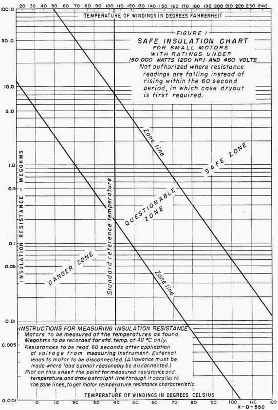
To avoid burn-outs due to damp insulation, it is necessary to know how to determine when the insulation is too damp to be safe. This can be done by measuring the insulation resistance and comparing it with the data in Figure 1. The insulation resistance should be measured by means of a megohmmeter which can read up to at least 5 megohms. If the winding is wet, a low-voltage ohmmeter operating on 6 to 45 volts is preferable to a megohmmeter as its voltage may be too high to be safe to use. The insulation resistance testing procedure given in FIST Volume 3-1 is intended for use on large equipment.
For tests on small motors, it is sufficient to take only one resistance reading after 1 minute application of the test voltage as covered in the instruction on Figure 1.
Some further instructions are given here for using Figure 1. The insulation resistance varies greatly with temperature and the temperature should be observed at the time the resistance measurement is made and corrected to the standard 40 EC temperature so as to have a uniform basis for comparison.
After taking the resistance and temperature measurement of the motor winding insulation and plotting it on Figure 1, as instructed thereon, this measurement will be found to be in a safe, a questionable, or a dangerous zone, depending upon the amount of moisture in the insulation.

Drawing a pencil line through this point parallel to the zone lines gives a resistance-temperature curve from which insulation resistance at any other temperature can be determined. The pencil line should be followed to the standard temperature line of 40 EC (104 EF), and a permanent record made of it so that winter and summer measurements can be compared without large errors due to temperature effects.
The differences in the insulation resistances as measured from time to time, and reduced to this standard temperature thus gives a true picture of whether the insulation resistance is improving or deteriorating. Readings from different ohmmeters or at different voltages should be avoided, although such errors may not exceed about 20 percent. The standard procedure is to make the insulation resistance tests with all motor leads disconnected except those which would involve too much trouble of unsoldering and untaping of joints. The chart applies strictly to motors without any leads connected. Where cables to the motors are short, new, or dry, the insulation resistance of these cables which is in parallel with that of the motor winding will usually have only a small effect.
The test data should note when leads are included in the measurement. Each measurement, corrected to the standard 40 EC temperature, should be recorded and used as a permanent “benchmark” for future reference. Any large variations from similar motors should be viewed with suspicion. All questionable or low readings should be further investigated by untaping or unbolting the cables not usually disconnected for this test, so as to locate and identify the cause for such low readings. Suitable steps should be taken to eliminate the cause of the low readings.
Rm = Vt + 1
Where:
- Rm = recommended minimum insulation resistance in megohms at 40 EC of the entire machine winding
- Vt = rated machine terminal to terminal potential in, rms, kilovolts
The winding insulation resistance obtained by applying direct potential to the entire winding for I minute must be corrected to 40 EC to be used for comparison with the recommended minimum value of Rm. The insulation resistance of one phase of a three-phase armature winding with the other two phases grounded is approximately twice that of the entire winding. Therefore, the resistance of each phase, when the two phases are tested separately, should be divided by two to obtain a value which, after correction for temperature, may be compared with Rm.
If guard circuits (a low-impedance bypass around the current meter) are used on the two phases not under test when each phase is tested separately, the observed resistance of each phase should be divided by three to obtain a value which, after correction for temperature, may be compared with Rm.


marine motors allowed to cool while the engine room is cooling down tend to absorb little moisture. However, the old practice of installing external motor heaters artificially raises the temperature of the motors to keep them “dry.” The problem with this practice is that electrical power is often interrupted during shipyard periods and at times when the engine room is a low temperatures and high humidity. The result is that the hot motor tends to absorb more moisture during these periods than if they had simply been left alone. If a motor’s insulation is somewhere between 500MOhms and Infinite, wouldn’t it be more reasonable “not” to put external heaters on the motors? It would also remove a potential fire and shock hazard. Thoughts?
Canned motors ( squirell cage induction) are frequently faling because of moisture.
Please give suggestions
Very useful technical information. Thank You for sharing it.
before and after varnish motor need to baking,it is helpful of vapourizing the moisture.