
Estimated Study Time: 4 minutes
11kV Indoor distribution substation
The following layout designs of indoor distribution substation are typical only and should not be used as construction drawings as they are presented as an example. Some designs achieve minimum EMF emission by installing the low voltage cables and switchboard in a trench down the middle of the room.
 7 typical layout designs of 11kV indoor distribution substation (photo credit: fima.lt)
This adds substantially to the space requirements. It is possible to reduce this space but only by sacrificing EMF containment!
The substations are designed for rated voltage 11 kV and 1500 kVA transformers. The space requirements for 22 kV padmount transformers need to be checked and it depends on manufacturer.
A drainage pit outside the substation is shown as optional. It can be installed if drainage is an issue or if needed to ease cable installation. Each substation is unique and the space requirements shown in the sample layouts may not be available.
The following rules should be followed when designing odd shaped substations:
- Size of transformer = 2000 × 2000 mm
- Transformer clearance to walls and other transformers = 500 mm
- Allow room to replace any transformer whilst other equipment is alive.
- LV and HV switchgear:
- clearance at front = 1500 mm
- clearance at sides = 500 mm
- The LV and HV switchgear should be near the door.
- A clear passageway at least 1000 mm wide shall be allowed from each item of switchgear to the access door.
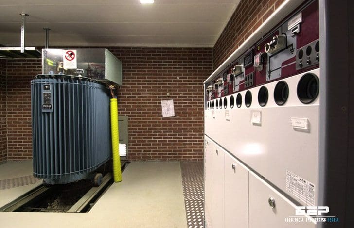
Layout design drawing 1
Indoor distribution substation layout with:
- 1 transformer
- LV switchboard
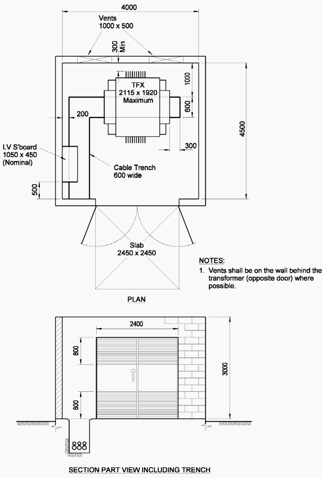
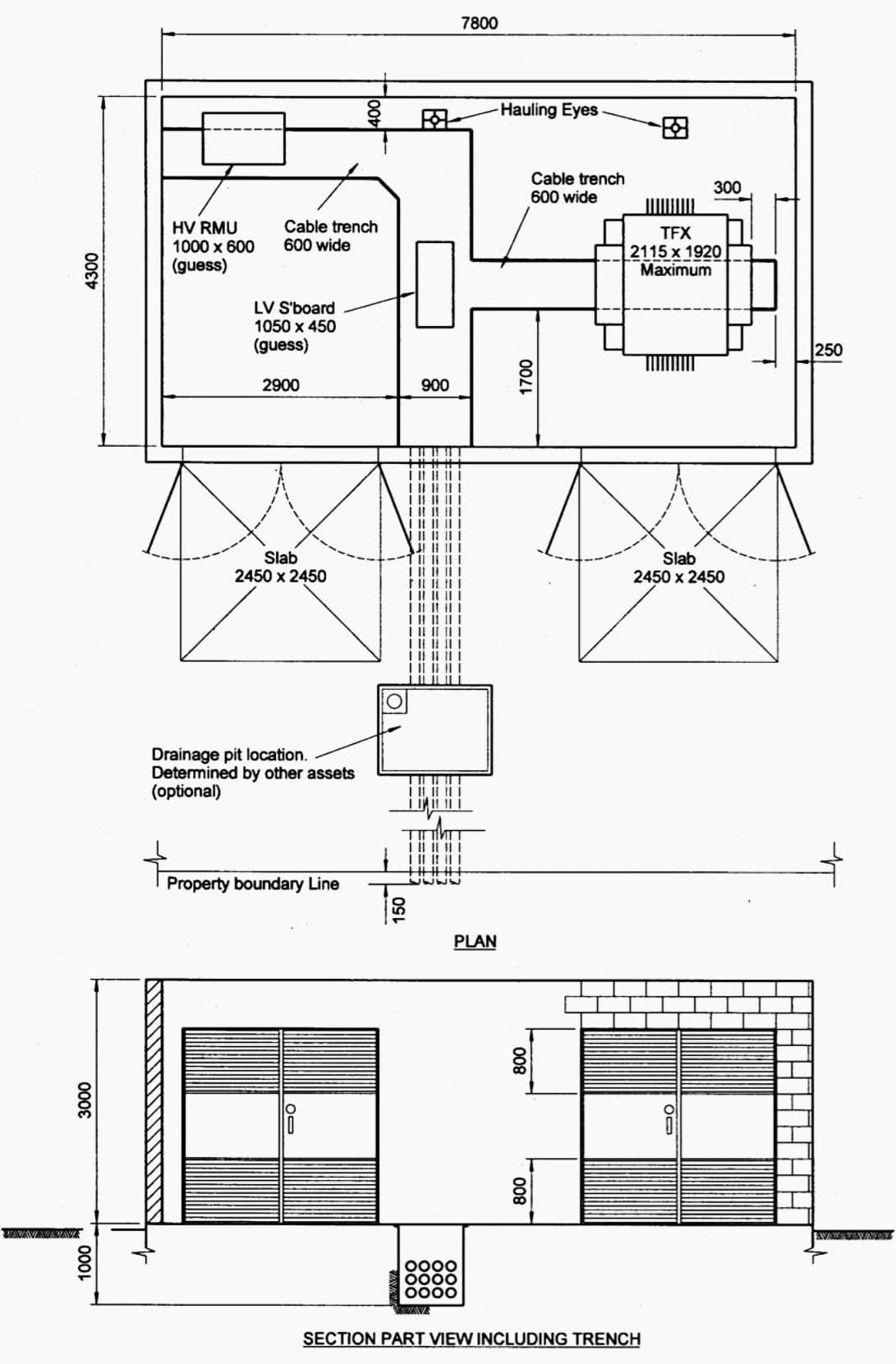
Layout design drawing 2
Indoor distribution substation layout with:
- 1 transformer
- LV switchgear
- HV switchgear (RMU – Ring main unit)
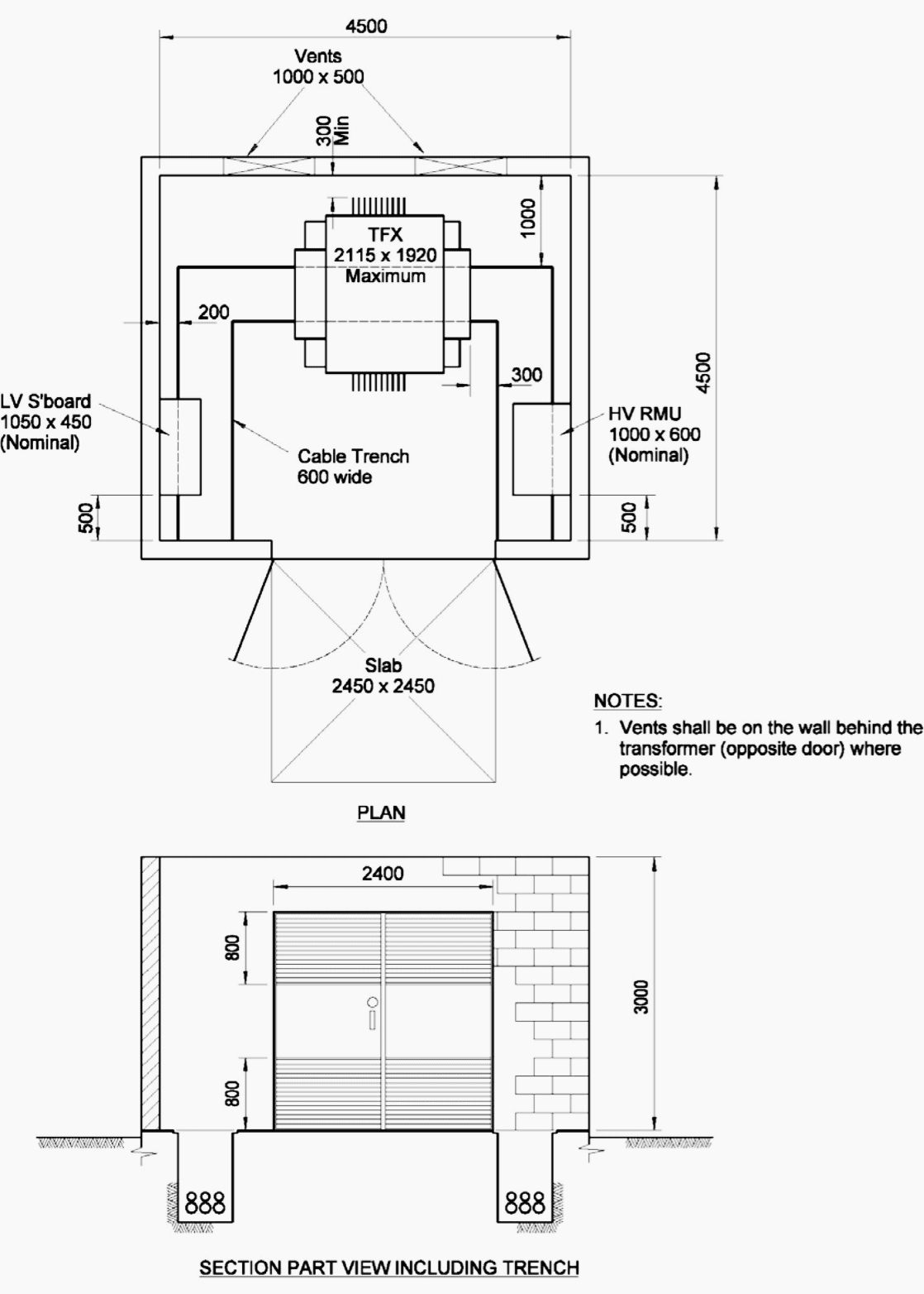
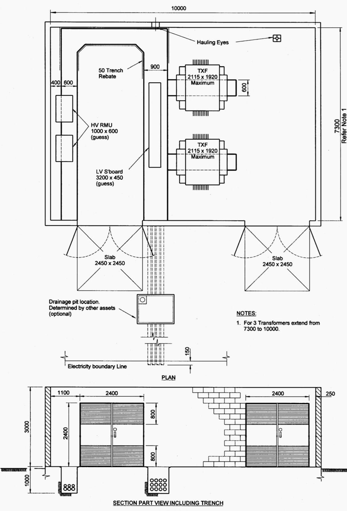
Layout design drawing 3
Indoor distribution substation layout (OPTION A) with:
- 3 transformers
- LV switchgear
- HV switchgear (RMU – Ring main unit)
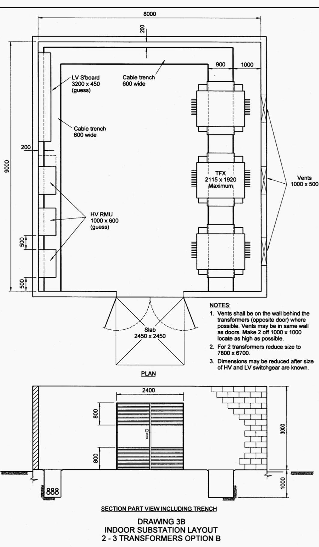
Layout design drawing 4
Indoor distribution substation layout (OPTION B) with:
- 3 transformers
- LV switchgear
- HV switchgear (RMU – Ring main unit)
Layout design drawing 5
Indoor distribution distribution substation layout with:
- 1 transformer with EMF contaiment
- LV switchgear
- HV switchgear (RMU – Ring main unit)
Layout design drawing 6
Indoor distribution substation layout with:
- LV switchgear
- HV switchgear (RMU – Ring main unit)
- 2 transformers with EMF containment
- 1 external wall
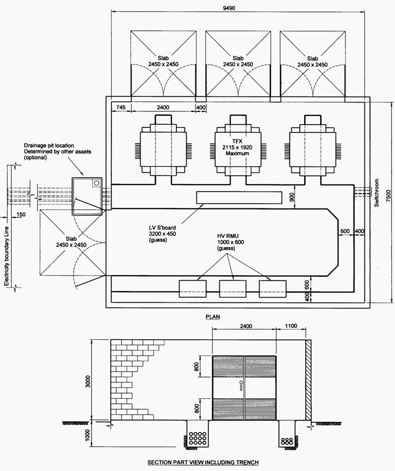
Layout design drawing 7
Indoor distribution substation layout with:
- LV switchgear
- HV switchgear (RMU – Ring main unit)
- 3 transformers with EMF containment
- More than 1 external wall
Reference // Indoor distribution substation design standard by Ergon Energy
Related electrical guides & articles


Edvard Csanyi
Hi, I'm an electrical engineer, programmer and founder of EEP - Electrical Engineering Portal. I worked twelve years at Schneider Electric in the position of technical support for low- and medium-voltage projects and the design of busbar trunking systems.I'm highly specialized in the design of LV/MV switchgear and low-voltage, high-power busbar trunking (<6300A) in substations, commercial buildings and industry facilities. I'm also a professional in AutoCAD programming.
Profile: Edvard Csanyi

Insightful! got all the information I was looking for, keep up the good work.
I am request to 11 kv sub station layout with material.
Ground Floor for Transformer and FF for Switchgear Room
what is the name of that thing that brings out smoke in substation when theres fire?
** 1500 mm space is inadequate. It suggested to be 1000mm after leaving breaker in racked out position or this is as in regulatory requirement as well.
As per Indian Standards and, C. E. A. Safety Regulations and Rules 2010; there shall be minimum clearance between wall and equipment either less than 200 mm or more than 750 mm with height of not less than 2100 mm
What shall be the Fire Rating of Doors? Whether these transformers are Dry Type or Oil filled type? If Oil filled type, what shall be the location in the building?
Please provide these details also for completeness of the a very good drawing / document prepared by you.
Regards.
What shall be the Fire Rating of indoor substation walls?
good information. tq for it. can i use this as example for my task?
The page is very educative and good informative. Keep up this good work
I NEED AN INFORMATION ABOUT AUTO CAD ELECTRICAL DRAWINGS
Hi,
I designed 2 rooms for 9 transformers one room contains 5 transformers and the second room contains 4 transformers of 1.5 KVA is that possible.how can I send this drawing to you.and please rate them to me
Regards.