
Estimated Study Time: 9 minutes
Instrument and protection CTs
Current transformers are used to supply information to the protective relays and/or current, power and energy metering “instruments”. For this purpose they must supply a secondary current proportional to the primary current flowing through them and must be adapted to network characteristics: voltage, frequency and current.
 Learn How To Specify Current Transformers (photo credit: naswgr.net)
They are defined by their ratio, power and accuracy class. Their class (accuracy as a function of CT load and of overcurrent) is chosen according to the application.
A “protection” current transformer (CT) must saturate sufficiently high to allow a relatively accurate measurement of the fault current by the protection whose operating threshold can be very high. Current transformers are thus expected to have an Accuracy Limit Factor (ALF) that is usually fairly high. Note that the associated “relay” must be able to withstand high overcurrents.
An “instrument”current transformer (CT) requires good accuracy around the nominal current value. The metering instruments do not need to withstand currents as high as the protection relays. This is why the “instrument” CTs, unlike the “protection” CTs, have the lowest possible Safety Factor (SF) in order to protect these instruments through earlier saturation.
The matching of CTs with protection relays calls for a thorough knowledge of current transformers. The following section gives a few reminders of CTs corresponding to this use.
Characterisation of CTs
An example of a protection CT //
- Rated primary current: 200 A,
- Rated secondary current: 5 A.

Its accuracy load: Pn = 15 VA
Its accuracy limit factor is ALF = 10
For I = ALF. In, its accuracy is 5% (5P), (see figure 1)
To simplify, for the protection CT given in example, the ratio error is less than 5% at 10 In , if the real load consumes 15 VA at In. However these data are not sufficient. Also, it is useful to know the standard values.

12 definitions related to current transformers //
- Rated (nominal) primary current I1
- Rated (nominal) secondary current I2
- Ratio (I1 / I2)
- Accuracy load
- Rated (nominal) accuracy power Pn
- Real power Pr
- Accuracy class
- Special accuracy class
- Real accuracy factor (Fp or Kr)
- Accuracy limit factor (ALF or Kn)
- Short time withstand current
- CT rated voltage
≡ Rated (nominal) primary current I1
Defined by standards, it is chosen from the discrete values: 10 – 12.5 – 15 – 20 – 25 – 30 – 40 – 50 – 60 – 75 A and their decimal multiples.
≡ Rated (nominal) secondary current I2
Equals 1A or 5 A.
≡ Ratio (I1 / I2)
The primary and secondary currents are standard, thus these values are discrete. (Learn more about ratios of magnetic HV instrument current transformers – Here)
≡ Accuracy load
Load value on which the accuracy conditions are based.
≡ Rated (nominal) accuracy power Pn
Expressed in VA, it is the apparent power supplied to the secondary circuit for the nominal (rated) secondary current and the accuracy load. The standard values are: 1 – 2.5 – 5 – 10 – 15 – 30 VA.
≡ Real power Pr
In this technical article, it is the power corresponding to the real load consumption of the CT at In.
≡ Accuracy class
This class defines the error limits guaranteed on the ratio and on the phase shift in specified power and current conditions. For the nominal 5P and 10P classes, the table in figure 6 defines these limits.
Figure 2 // Errors on the module and the phase at nominal current
(according to standard IEC 60044-1)
| Accuracy class | Current error for the nominal current as a % | Phase shift for the nominal current | Composite errors for the accuracy limit current as a % | |
| Minutes | Centiradians | |||
| 5P | ± 1 | ± 60 | ± 1.8 | 5 |
| 10P | ± 3 | – | – | 10 |
≡ Special accuracy class
Class X is a class defined by British standard BS 3938. It must also be defined in the future standard IEC 60044-1 under the name of class PX. This class specifies the minimum value of the knee point voltage Vk of the CT.
It also imposes a maximum value of Rct (CT secondary winding resistance). Sometimes, it specifies the maximum value of the magnetising current Io at knee point voltage.
If we consider the magnetising curve V(Io) of the CT, the knee point voltage Vk is defined as the point on this curve from which a 10% increase in voltage causes a 50% increase in the magnetising current Io. Class X corresponds to a better metering accuracy than classes 5P and even more so 10P (see figure 3).

It is always possible to find an equivalence between a CT defined in class X and a 5P CT or in some cases even a 10P CT.
≡ Real accuracy factor (Fp or Kr)
This is the ratio between the overcurrent corresponding to the nominal error and the rated current of the CT when the real load is different from the nominal load.
≡ Accuracy limit factor (ALF or Kn)
This is the ratio between the nominal overcurrent (e.g. 10 In) and the rated current (In).
≡ Short time withstand current
Expressed in kA, this is the maximum current Ith that can be withstood for one second (when the secondary is short-circuited). It represents the thermal withstand of the CT to overcurrents (the standard values are given by the standards mentioned in the appendix).
≡ CT rated voltage
This is the rated voltage to which the CT primary is subjected. It is important to remember that the primary is at HV potential and that one of the terminals of the secondary (which must never be opened) is normally earthed.
Just as for any devices, a maximum withstand voltage for one minute at power frequency and a maximum impulse voltage withstand are also defined. Their values are defined by the standards.
For example: for a rated voltage of 24 kV, the CT must withstand 50 kV for 1 minute at 50 Hz and 125 kV at the impulse voltage.
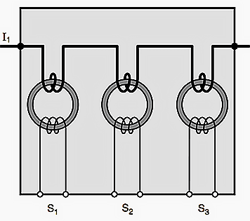
CT with several secondaries
Some current transformers may have several secondaries dedicated to protection or to metering. The most typical cases are CTs with 2 secondaries, more rarely with 3 secondaries. Physically, these CTs group in the same mould the equivalent of 2 or 3 separate CTs that can have different classes and ratios (see figure 4 below).
Current transformers – VIDEO sessions
What are CTs and why use them?
CT Polarity
CTR
Wye connected CTs
Delta connected CTs
Current transformer model
Reference // Cahier Technique Schneider Electric no. 194 – Current transformers: how to specify them by Schneider Electric
Related electrical guides & articles


Edvard Csanyi
Hi, I'm an electrical engineer, programmer and founder of EEP - Electrical Engineering Portal. I worked twelve years at Schneider Electric in the position of technical support for low- and medium-voltage projects and the design of busbar trunking systems.I'm highly specialized in the design of LV/MV switchgear and low-voltage, high-power busbar trunking (<6300A) in substations, commercial buildings and industry facilities. I'm also a professional in AutoCAD programming.
Profile: Edvard Csanyi

Your article is always useful and interesting. I thank you and wish you good health
How we can find Rct and Imag for PS class CT?
Hi Edvard,
For Low Impedance REF, is there a disadvantage of using a CT with higher magnetisation current at knee point voltage compared to lower one. From my understanding high magnetisation current leads to high CT error. How would this affect the Low Impedance REF relay?
Hi Edvard,
Excellent you are doing a great work.
Thanks for sharing all this invaluable and useful information.
Thanks®ards
Imed.
Thank you Imed.
Hi Edvard, Very usefull information! I have a client who wants to substitute the pre-defined Class X CT with an existing 5P20 CT due to space constraints. Are there any special considerations required by substituting a Class X CT (on diff protection) with a 5P20 CT specified for OC/EF protection?
Jan
You work great and bring us great benefit through your topics
Excellent!
Info is very impressively.
Where is Rct? How this is calculated? A detail must be given here.
Excellent!
Sir.i am very impressed your information
Hi Edvard, Thank you for all this invaluable information and clarity you provide.
Could you do an article for System Studies on a Distribution Network?
What’s the main difference between CT of protection and CT of metering?
Hi.. I want to know how you are selecting the Magnetizing current limits for the knee point ( e.g) Vk=30mA , 45mA or .etc… and where the Vk , Vk/2 , Vk/4 are applicable / selected .? Very urgent .. please reply sir..
Have you got an answer for that question ? Cuz I got the same inquiry from a client
Sir I would like to know the difference between PS class, PX clear, TPX, TPY, TPZ. Please explain.
Info is very impressively
Dear EDVARD sir, The technical information which you are providing is very useful
Bismillah.
How to get the PDF version of this article?
See the blue button on your left ‘Get PDF’ and follow the simple instructions. This makes PDF for you.
Thank you! I think should open it by using desktop/laptop.
Yes, sorry I didn’t mention this information. On mobile it’s not available.
As always, the info is very impressively put together. Thanks man.
Further could you take up following topics:-
1. Metering CT: How to select a CT for an application. For eg. if we have a load of 400A on a source than can provide 800A, then should we go for a 400/1 CT, 600/1 CT or 1000/5 CT.
2. Effects of Under sizing, Over sizing the CT
3. CT callibration. Why and how ?
I ask this because I am dealing with an environment where we have variable load. The load increases, reaches peak and decreases over a period of time.
So would we be needed to change the CTs also with the load ?
Select the CT based on the size of the highest load rating / current rating the respective bus bar rating.
No adverse effect of over sizing.
Standard CT shall be procured based on calibrated by authorized agency.
Hello,
Could you talk about US standards based current transformers . Please make distinction between US and IEC ratings — so it is easy for reader to understand the different electrical markets.
Sir, I am very much impressed about ur site informations.
Thank you Sathish!