
Estimated Study Time: 27 minutes
Detailed analysis of disturbances
In addition to the known phenomena of lightning and switching, numerous new sources, in particular power converters, can cause disturbance in installations. This disturbance, which is generated by the installation itself or carried by the system from external sources or by the conductive parts, earthing circuits and shared elements, depends on the characteristics of the installation (impedances, short-circuit power, resonance, etc.).
 Six less known phenomena that can cause disturbance in electrical installations
The complexity of all these EMC phenomena makes them difficult to predict and even more difficult to simulate.
There are various aspects of electromagnetic compatibility (EMC) that are very important, including protection against lightning phenomena, the principles of building installations for aspects of equipotentiality, shielding and coupling between conductors, taking harmonics into account and the effect of the choice of the neutral earthing system on EMC.
The effects of overvoltage and rapid voltage transients (capacitor switching, overvoltages caused by converters, restrikes, failure of fuses, etc.) that are mainly encountered in industrial or commercial environments.
Phenomena generated by receivers (DC components, leakage currents, discharge on the system, etc.), which can all affect the quality of the energy used, whether it comes from a public distribution system or any other origin.
- Operational switching: overvoltages and overcurrents
- Disturbances caused by static converters
- Switching overvoltages of capacitors
- DC components
- Permanent leakage currents
- Current inversion
1. Operational switching: overvoltages and overcurrents
Although these types of disturbance are mentioned in standard EN 50160, in which overvoltages are treated in terms of impulse withstand voltage (Uimp) to be applied when designing switchgear in order to protect against their possible destructive effects, they are also sources of potential malfunctions.
Their very broad frequency spectrum, their random occurrence and their many forms make them difficult to eliminate. In fact, practically all operations on industrial systems, in particular high power operations, produce overvoltages.
The above oscillogram shows the voltage bounces and peak voltages that may occur for example when a fluorescent lighting circuit is energised.
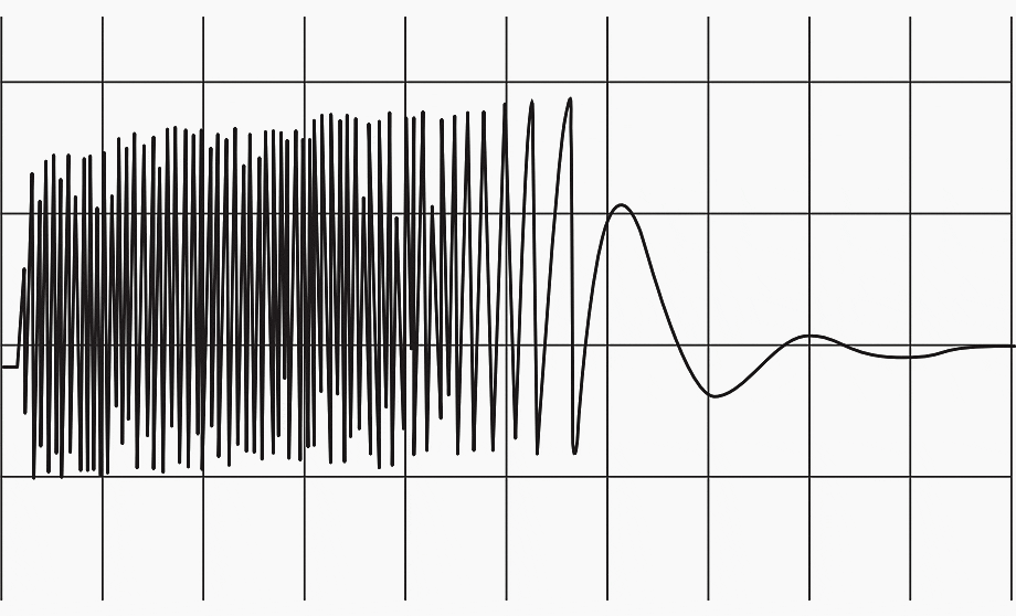
This type of disturbance is often accompanied by an overcurrent on the line concerned and emission of magnetic and electric fields.
Due to the size of the LF transient current (10 kHz < f < 1 MHz) on closing, the radiated impulsive magnetic field can reach high values that may disturb sensitive products. If the overcurrent involved is high (several kA), the damped oscillatory magnetic field caused by the disturbance can be simulated in order to check the immunity of sensitive products.
Although closing operations are accompanied by high overcurrents and generally limited overvoltages, opening operations trigger overvoltages than can be very high. They can be accompanied by high frequency electric fields that could cause disturbances.
The phenomenon of resonance plays a major role here. Breaking the current in an electric contact generates damped oscillations at the resonance frequencies of the source and the load. The resonance frequency of the source is very often higher than that of the load.
Transients caused by the load and the source are superimposed, leading to high voltage levels at the terminals of the electric contact. If they exceed the voltage withstand of the contact, an electric arc is created. A voltage collapse is then observed at the terminals, while the current continues to circulate (this is referred to as non-limiting self-extinguishing current). The arc ends when the electrical and thermal stresses on the contact are not sufficient to maintain it.
The voltage transients during the switching phase oscillate at frequencies between 10 kHz and 10 MHz. The peak voltages of these transients range from a few hundred volts to several kilovolts.
Standard IEC 61000-4-4 (electrical fast transient/burst immunity test) can be used to test equipment and appliances when coupled to their power supply access.
To limit overvoltages and overcurrents during operations, it is essential to choose breaking devices that act very quickly and independently of the manipulation speed. They must be suitable for the loads.
Standard IEC 60947-3 (switches, disconnectors, switch-disconnectors and fuse-combination units) specifies the various utilisation categories for typical applications.
Table 1 – Utilisation categories for switches, disconnectors and fuse-combination units according to IEC 60947-3
| Type of current | Utilisation category | Typical applications | |
| Category A | Category B | ||
| AC | AC-20Aa | AC-20Ba | Connecting and disconnecting under no-load conditions |
| AC-21Aa | AC-21Ba | Resistive loads, including moderate overloads | |
| AC-22Aa | AC-22Ba | Mixed resistive and inductive loads, including moderate overloads | |
| AC-23Aa | AC-23Ba | Motor loads or other highly inductive loads | |
| DC | DC-20Aa | DC-20Ba | Connecting and disconnecting under no-load conditions |
| DC-21Aa | DC-21Ba | Resistive loads, including moderate overloads | |
| DC-22Aa | DC-22Ba | Mixed resistive and inductive loads, including moderate overloads (for example: shunt motors) | |
| DC-23Aa | DC-23Ba | Highly inductive loads (for example: series motors) | |
Category a applies to equipment for frequent use, while category B applies to equipment for occasional use.
1.1 Installing voltage surge protectors
Installing voltage surge protectors, designed to provide protection against overvoltages from the lightning effects, makes it possible to protect against the destructive effects of switching overvoltages which are more frequent but generally at a lower level than those due to lightning.
However the sparkover operating principle of these devices creates impulse currents in the bonding and earthing systems which are references for sensitive systems.
Their installation is therefore recommended for optimum protection, but it does not in any way dispense with the need for all the other measures designed to minimise these overvoltages.

1.2 Typical switching overvoltage curves
Transient states, which may be the source of overvoltages and overcurrents, can occur when loads are switched on or off. the most common transients concern transformers, motors, capacitors and batteries.
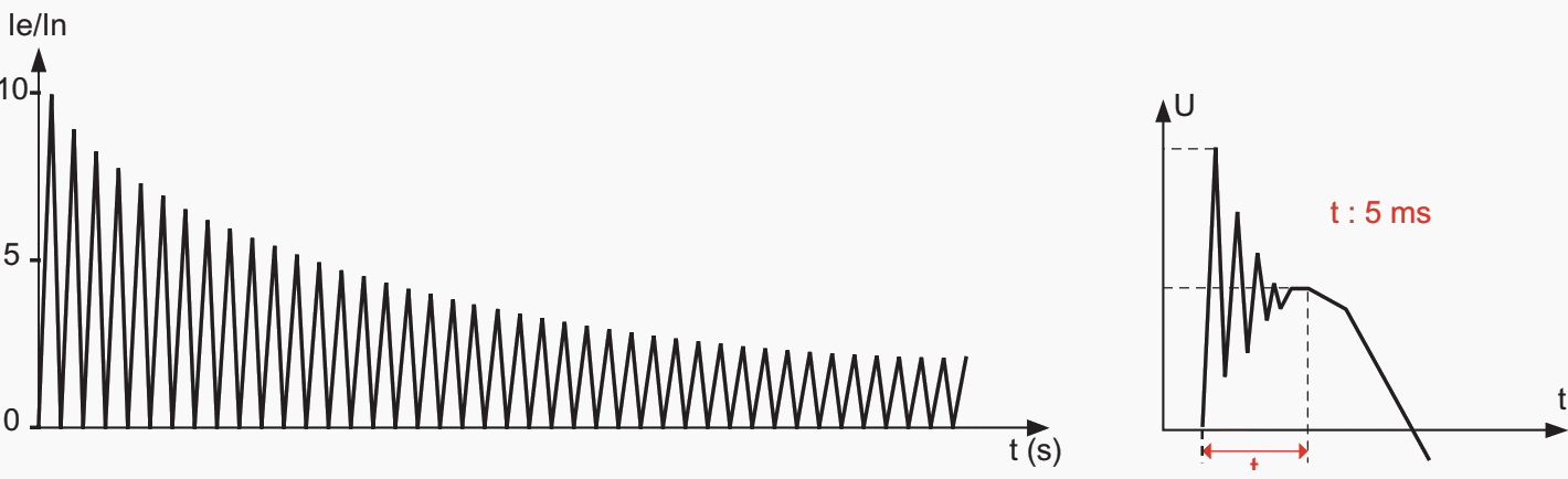
Activating a transformer causes an inrush current of 10 to 20 In with a damped aperiodic component. this triggers an overvoltage in the secondary by capacitive coupling, and oscillatory effects due to the capacitances and inductances between the turns.
The breaking (or opening) of a transformer creates a transient overvoltage due to the breaking of the current in an inductive circuit. this overvoltage can create arc restrikes in the breaking devices, which must be chosen accordingly.

1.3 Electrical resonance
The phenomenon of electrical resonance is frequently found in installations. It can lead to destructive overvoltages and overcurrents.
Three types of receivers make up AC electrical circuits : resistors (in ohms), capacitors (in farads) and inductors (in henrys). The impedance Z of these receivers (which is also expressed in ohms) is a function of the frequency f (hz), of the power supply signal and more precisely of its angular frequency ω= 2π×f (expressed in radians per second) and is expressed respectively in the forms ZR = R, ZC = 1/Cω and ZL = Lω.
It is important to distinguish series resonance phenomena from parallel resonance phenomena.
1.3.1 Resonance of a series RLC circuit

In a capacitance C, the current is in π/2 phase lead in relation to the voltage (lead quadrature) in an inductance L, the current is in π/2 phase lag in relation to the voltage (lag quadrature).
Lω = 1/Cω which can also be written LCω2 = 1.
ω is the resonance angular frequency, which is generally written 0 and the resonance frequency f0 is equal to ω0/2π.
When there is resonance, the impedance of the circuit is practically the same as its resistance R. If the resistance is low (low resistance circuits such as distribution lines), the situation becomes critical.
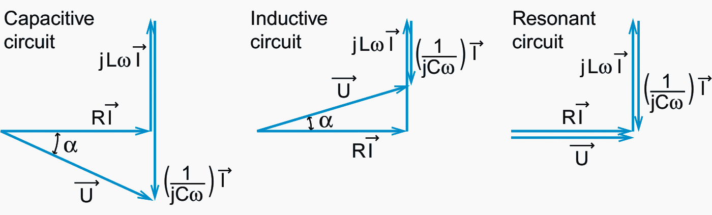
The voltage applied at the terminals of the circuit then creates a very high current. this current then imposes voltages UC and UL at the C and C terminals, which may exceed their withstand and cause dielectric breakdown.
The properties of series RLC circuits are used to create filters.
1.3.2 Resonance of a parallel RLC circuit
The same phenomena occur on parallel RLC circuits. But in this case it is not the current which is common to all three elements, but the voltage U.
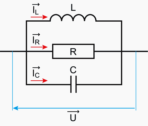
The effects of the resonance differ according to whether it is series or parallel, and depending on whether the source behaves like a voltage source or a current source.
An ideal voltage source maintains a constant voltage at its terminals irrespective of the current drawn. For small or medium sized consumers, the distribution supply network behaves like a voltage source. a high capacitance behaves like a voltage source for a reduced load (high resistance).
In practice, industrial systems are complex and comprise both parallel and series elements (these are the receivers and also the conductors, the transformer windings, the stray capacitances, the leakage resistances, etc.) which represent both inductances and capacitances.
It is thus always possible that resonance may occur, and adding compensation capacitors may modify or trigger the conditions for their occurrence.
2. Disturbances caused by static converters
Power electronics has gradually become established as the preferred method of controlling electrical energy. Originally used almost exclusively for varying speed or torque control applications, it has now spread to the field of the low power switching mode power supplies that are found everywhere, and in the future it will play a decisive role in the control and stability of smart electrical systems whose energy production with be both mixed and decentralised. (Smart grid).
Unlike operational switching, described in above paragraphs, which is characterised by its more or less random and non-repetitive occurrence and by characteristics mainly due to loads and installations, that caused by static converters is recurrent.
In fact, each conversion stage contributes to disturbance over a frequency range that is dependent on its switching frequency: input rectifier up to a few dozen kHz, HF switching stage up to a few megahertz and phenomena associated with the switching transitions (resonance, normal mode excitation) up to several dozen megahertz.
EMC treatment of converters will consist of limiting their spectral range or trying to confine all the undesirable parasitic effects in the converter.

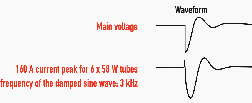
A three-phase sinusoidal voltage is generally rectified using a thyristor bridge. The load current is drawn at the three phases by alternate operation of the thyristors. These are “trigged” in succession by the thyristor that was in control in the preceding time phase sending a pulse to their gate.
The result is periods, which are of course very short (a few hundred µs), in which short-circuits occur between phases.
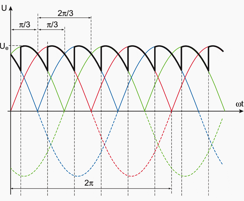
The value of these short-circuits is only limited by the impedance of the upstream system. The effect of the inrush current is voltage drops and voltage increases that are referred to as “commutation notches”.
Rather than their amplitude, it is above all the differentials of these values (dV/dt), which may reach several hundred V/s, that cause electromagnetic disturbances. The resulting high frequencies may encounter resonance in the system, in particular in the presence of capacitances (cables, capacitors), and result in this case in real overvoltages on the system.

3. Switching overvoltages of capacitors
The activation of capacitors placed on the MV system may cause transient overvoltages (several times the value of Un) with sufficient energy to destroy the voltage surge protectors at the supply end of the low voltage installation or even the components of the static converters or reactive energy compensation capacitors.
The characteristics of this phenomenon are essentially linked to the inductance L of the MV/LV transformer, the capacitance C of the capacitors and the resistance R of the low voltage network. If the resistance is low (not many resistive receivers), the damping of the transient overvoltages will be reduced, increasing the risk of resonance on the MV and LV circuits at the same frequency.
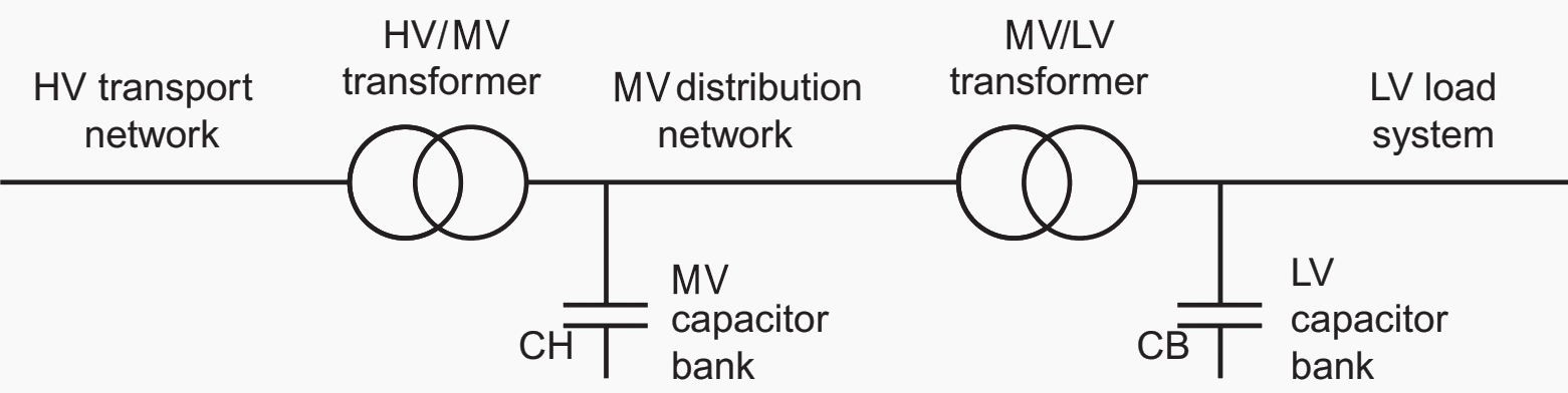
Amplification of the disturbance associated with MV capacitor switching is particularly sensitive if the reactive power used in MV is much higher than that used in low voltage. This risk can be limited by using capacitor banks that are activated gradually (steps) or by activation at zero voltage.
High energy absorption (at least 1 kilojoule) voltage surge protectors can be used to limit transient overvoltages from the MV system, in the same way as tuned filters with low voltage capacitor banks can shift the resonance frequency of the installation.
Overvoltages from the MV system will not be eliminated, but at least they will not be amplified.
Guide To Medium Voltage Capacitor Bank Switching And Impact Of Overvoltage On The System
4. DC components
The electronic supply stage of numerous machines and also many high consumption domestic appliances (washing machines, hobs, etc.) has a rectifying device. If there is an insulation fault downstream of this device, the earth leakage current may contain a DC component (more precisely a unidirectional pulsed component) which modifies the shape of the AC current consumed.
The toroidal core may then remain magnetised (hysteresis phenomenon) and the residual current device is rendered inoperative.
AC type residual current devices (RCDs), used for the majority of circuits, cannot detect this type of fault. They should only be used for heating or lighting circuits that do not have an electronic power supply.

New residual current devices have been developed to operate with electronically controlled loads.
- Type “A” RCDs protect against sinusoidal AC fault currents and fault currents with a pulsed DC component.
- Type B RCDs also provide protection against smooth DC fault currents. These are mainly used in industry, on three-phase installations containing for example variable speed drives or an uninterruptible power supply (UPS).
5. Permanent leakage currents
Unlike fault currents, which flow accidentally between the live poles and the protection circuit or earthing, leakage currents exist while the installation is operating normally.
There are three different types of leakage current:
Leakage current #1
Currents caused by receivers whose power supply is earthed (via bonding parts and the protection circuits) by means of capacitive electronic components (PCs, variable speed drives, etc.).
On energisation, these currents are increased by an inrush current phenomenon associated with the load of the capacitors. Some typical potential leakage current values are given the the table below.
Leakage current #2
Currents that are associated with stray capacitances from the installation’s conductors which are proportional to the scale of the installation and the number of receivers supplied.
There are no exact rules for calculating these currents other than that they can trip a 30mA residual current device when the installation reaches several hundred metres in length. It should also be noted that these currents may increase over time, depending on the ageing of the insulation.
Monitoring the installation’s insulation by means of continuous measurement (Permanent Insulation Monitor – PIM) or regular measurement enables any changes to be anticipated.
Leakage current #3
Leakage currents that frequently develop on certain types of installations due to their nature, without however reaching a dangerous level comparable to a fault current (resistance furnaces, cooking or steam installations, equipment with numerous auxiliaries or sensors, etc.).
Using the TN-S neutral earthing system limits the contact voltage to a value which is not dangerous, while permitting significant leakage currents to exist.
The design of an electrical installation must provide for the installation of protection devices for the safety of people and property which take account of these leakage currents.
When these currents are added together in the protection circuits they can reach the trip threshold value of the residual current protection at the supply end of the group of circuits concerned, remembering that this value is generally much lower than the theoretical threshold: for example 15 to 20 mA actual for 30 mA nominal.
Table 2 – Typical leakage current values
| Electrical appliance | Typical potential leakage current |
| Computer workstation | 1 to 3 mA |
| Underfloor heating | 1 mA/kW |
| Printer | < 1mA |
| Cooking appliances | 1.5 mA/kW |
6. Current inversion
Any installation connected directly to a public energy distribution system and that may also be supplied via another source should normally incorporate a device to prevent backfeed of the distribution system.
Increasing numbers of installations are carrying out self-generation based on renewable energies (solar or wind-powered production, small power plants or other sources) and are connected to the supply network to feed energy back into it.
This arrangement must of course form the subject of an agreement, as well as a number of precautions.
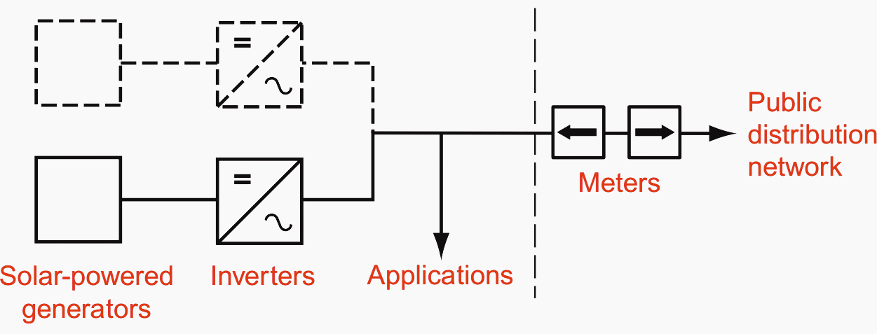
Decoupling protection must disconnect generators if the following occurs:
- Fault on the supply network
- Disappearance of the power supply via the supply network
- Voltage or frequency variations greater than those specified by the distribution company
This decoupling protection must be incorporated in an automatic breaking device that complies with a recognised European standard.
References:
- Legrand
- Electrical Power Systems – Roger Dugan
- Practical Grounding, Bonding, Shielding and Surge Protection – G. Vijayaraghavan, Mark Brown, Malcolm Barnes
Related electrical guides & articles


Edvard Csanyi
Hi, I'm an electrical engineer, programmer and founder of EEP - Electrical Engineering Portal. I worked twelve years at Schneider Electric in the position of technical support for low- and medium-voltage projects and the design of busbar trunking systems.I'm highly specialized in the design of LV/MV switchgear and low-voltage, high-power busbar trunking (<6300A) in substations, commercial buildings and industry facilities. I'm also a professional in AutoCAD programming.
Profile: Edvard Csanyi

I congratuled to the people that writed those articles that are high professional nivel in Electrical Engineer.
Regard
Henry Lanfranco
Lima Peru
You have a good ideology…… I would like to learn more from you as I struggle hard to being electrical engineer… Thank you
It’s article is very reliable for all electrical engineers
I really thanks to Mr Edward
Muchas gracias por toda la informacion que comparte…mi persona esta realizando mi tesis de maestria sobre Armonicos en instalaciones electricas comerciales. Es muy buena la informacion q comparten…si tuvieran alguna informacion mas especifica sobre el tema o sino sobre mantenimiento de sistemas electricos RCM…estare muy agradecido y si fuera en español mucho mas
Un saludo desde Bolivia – La Paz
I do think it is great and well done do take great care and have a lovely day
I would like to invite you to join my professional network at LinkedIn hear from you again
Regards a friend Johhann