
Estimated Study Time: 14 minutes
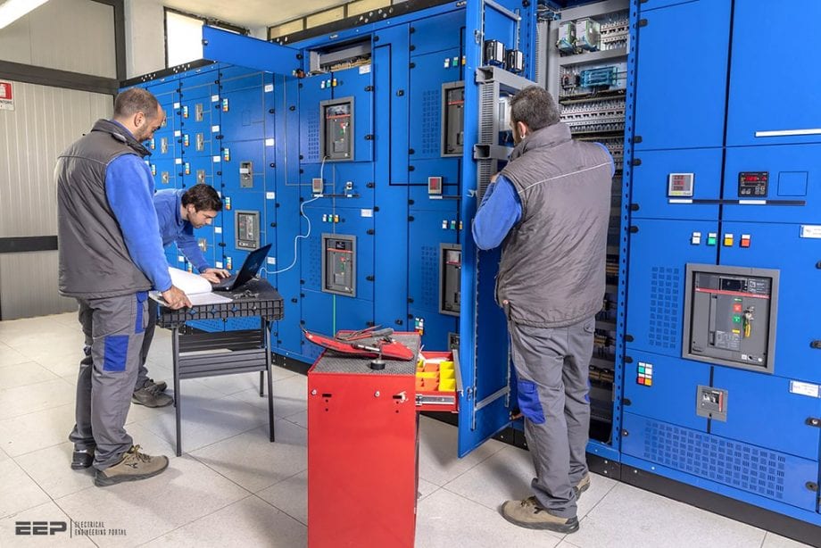
Low voltage switchboard
Let’s start with some basic definitions from the United States National Electrical Code (NEC). Low voltage switchboard is generally defined as a large single panel, frame, or assembly of panels on which are mounted on the face, back, or both, switches, overcurrent and other protective devices, buses, and usually instruments.
 Lessons I learned during installation and wiring of LV switchboard
These assemblies are generally accessible from the rear as well as from the front and are not intended to be installed in cabinets. Modern switchboards are totally enclosed to minimize the probability of spreading fire to adjacent combustible materials and to guard live parts.
Busbars are arranged to avoid inductive overheating of the enclosure or any nearby metal. Service busbars are isolated by barriers from the remainder of the switchboard to avoid inadvertent contact by personnel or tools during maintenance.
Here are some of the lessons I learned designing LV switchboards:
- Switchboards and panelboards are different
- Access
- Transport
- Housekeeping
- Insulating mats
- Location
- Architecture
- Layouts and clearances
- Breakers, fuses or both
- Metering
- Preplanning
- Coordination
1. Switchboards and panelboards are different
Switchboards are typically used for service entry, and any distribution required there onwards. On the other side, panelboards are used primarily for branch circuits, and end of line loads. It follows therefore that switchboards feed panelboards.
One key distinction to remember is that panelboards typically have a maximum ampacity of 800A to 1200A and are governed by Underwriters Laboratories’ (UL) 67 – Standard for Panelboards.
The designs of switchboards are governed by UL 891 – Standard for Switchboards.

2. Access
This is always a big issue. Most codes and regulations will require two ways to enter and exit the switchboard area, likely at each end of the switchboard lineup.
Always plan for a dedicated room for the switchboard.
Over a certain amperage, many codes and regulations have this specific exit requirement but it is an engineering best practice to do it anyway. If you think about it, in an emergency, the easiest way to get out of an area would be to just have to push your way out.
To further ease your way out, another key item with doors is that they should have ‘panic hardware’ on them.

3. Transport
Size your entry/exit doors to create a large enough opening that the switchgear can actually be brought into its dedicated room (or area) for installation. This seems obvious, but it is easily missed.
Pick the largest piece that needs to be transported! The manufacturer should be able to give you this information. Then work out an approximate path of how you believe that piece can get into the building and then into the room.
This is worked out by the installer; however, going through it as a designer helps prevent consternation later.
Related electrical guides & articles


Amar M
Electrical engineer specializing in the complete lifecycle (concept through to construction) of LV/MV designs as they pertain to the power requirements of various building types such as commercial, physical sciences, pharmaceutical, and others.Profile: Amar M
