
Estimated Study Time: 11 minutes
General about start-up
In the world of electrical engineering, a term start-up assumes all works which are necessary to be done for putting in operation already tested switchgear, as close as possible installed in position and ambient defined by design documentation and employer’s requirements.
 Lessons I learned during the start-up of an MV switchgear
In order for the start-up to be as more valid as possible, working parameters shall also be close to or equal to designed values. The start-up procedure usually begins with the power-up of the equipment and continues with signal checking, parameter fine adjustment, measurements control, etc.
For more details, you can see the previous article called ‘Most important precautions during commissioning and start-up of LV switchgear’.
These problems may be very expensive and/or require a lot of time to be solved, so in that way, the project time schedule or budget may be significantly jeopardized.
Moreover, in some cases, problems related to MV switchgear can cause problems related to other, downstream equipment, such as power transformer or LV switchgear.
Example of MV switchgear start-up problems
Within this article, a real example of 20kV switchgear, which belongs to (1000+1000) kVA industrial substation, will be shown. Experience gained through troubleshooting of problems that occurred during start-up will be shared, with adequate descriptions in the form of wiring diagrams.
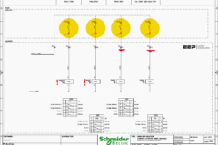
A simplified block diagram of major electrical equipment inside the substation is given in Figure 1.

MV switchgear (=14+1L) is of 8DJH type, made by Siemens, with major characteristics as presented in Table 1.
Table 1 – MV switchgear (=14+1L) rated values
| 8JDH Characteristics | Value |
| Rated voltage of equipment | 24 kV |
| Rated working (service) voltage | 20 kV |
| Rated busbar current | 630 A |
| Rated feeder current | 200 A |
| Rated short-time withstand current | 16 kA × 1 s |
MV switchgear consists of the following cubicles listed in Table 2 below.
Table 2 – MV switchgear (=14+1L) cubicles
| MV switchgear (=14+1L) cubicles | Qty. |
| Incoming feeder cubicle, with switch disconnector and earthing switch | 2 |
| Measuring cubicle, with voltage and current measuring transformers | 1 |
| Transformer feeder cubicle, with protection fuses, switch disconnector, and earthing switch | 2 |
Feeders with fuses are much less expensive than feeders with circuit breakers and relays. On the other hand, later are much more flexible and able to provide more comprehensive and sophisticated protection.
Besides, if not chosen correctly, fuses may cause problems during the start-up of the equipment with high initial currents, such as no-load power transformers or power capacitors.
Switch disconnectors inside transformer feeders can be opened in three possible ways:
- Manually, by inserting lever into opening on the cubicle and rotation in desired direction
- By opening mechanism excited by striker pin, which is released when the fuse is blown. In that way, disconnection of transformer from MV grid is provided in the case of severe overload or short circuit
- Electrically, by applying control voltage to shunt opening release
In this application, shunt opening release is designed to be excited when DGPT transformer relay is activated. Since activation of this relay implies serious transformer issue, it makes sense to disconnect it from primary supply.
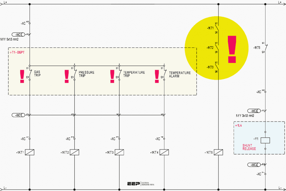
Initial protection logic is realized inside main LV switchgear (+1N) by wiring diagram given in Figure 2.

If all trip contacts on DGPT relay are inactive (closed), auxiliary relays (-1KT1, -1KT2, -1KT3) are excited, their output contacts are closed, and therefore auxiliary relay (-1KT5) is also excited, i.e. output terminals (11) and (12) are open.
Shunt release (+1L4-Y1) is disconnected from control voltage wires (L+, L-). If any of DGPT relay contact is activated (opened), relay (-1KT5) will be disconnected from control voltage, output contacts (11) and (12) will be connected, and shunt release will be excited, i.e. switch disconnector will be opened.
Related electrical guides & articles


Miodrag Kokotovic
Graduated from Faculty of Electrical Engineering, within University of Belgrade, in the field of electrical power systems. Expert in electrical part of tender preparation, design, procurement, construction and commissioning of treatment plants and pumping stations, electrical power quality and energy management.Profile: Miodrag Kokotovic
