
Estimated Study Time: 5 minutes
Lighting control system
A lighting control system is to be developed. The system will be controlled by four switches, SWITCH1, SWITCH2, SWITCH3, and SWITCH4. These switches will control the lighting in a room based on the following criteria:
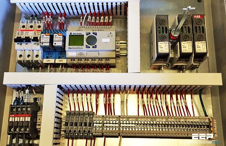 Let's develop the simple PLC program for lighting control system (photo credit: hoffman-mfg.com)
- Any of three of the switches SWITCH1, SWITCH2, and SWITCH3, if turned ON can turn the lighting on, but all three switches must be OFF before the lighting will turn OFF.
- The fourth switch SWITCH4 is a Master Control Switch. If this switch is in the ON position, the lights will be OFF and none of the other three switches have any control.
The wiring diagram //
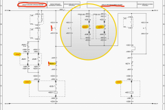
The first item we may accomplish is the drawing of the controller wiring diagram. All we need do is connect all switches to inputs and the lighting to an output and note the numbers of the inputs and output associated with these connections.
The remainder of the task becomes developing the ladder diagram. The wiring diagram is shown in Figure 1.
Notice that all four switches are shown as normally open selector switches and the output is connected to a relay coil CR1. We are using the relay CR1 to operate the lights because generally the current required to operate a bank of room lights is higher than the maximum current a PLC output can carry.
For this wiring configuration, the following definition list is apparent:
- INPUT IN1 = SWITCH1
- INPUT IN2 = SWITCH2
- INPUT IN3 = SWITCH3
- INPUT IN4 = SWITCH4 (Master Control Switch)
- OUTPUT OUT1 = Lights control relay coil CR1
This program requires that when SWITCH4 is ON, the lights must be OFF. In order to do this, it would appear that we need a N/C SWITCH4, not a N/O as we have in our wiring diagram. However, keep in mind that once an input signal is brought into a PLC, we may use as many contacts of the input as we need in our program, and the contacts may be either N/O or N/C.
Therefore, we may use a N/O switch for SWITCH4 and then in the program, we will logically invert it by using N/C IN4 contacts.
The ladder diagram to implement this example problem is shown in Figure 2.

The ladder was printed using graphics characters (extended ASCII characters).
Notice the normally closed contact for IN4. A normally closed contact represents an inversion of the assigned element, in this case IN4, which is defined as SWITCH 4. Remember, SWITCH 4 has to be in the OFF position before any of the other switches can take control. In the OFF position, SWITCH 4 is open.
This means that IN4 will be OFF (de-energized). So, in order for an element assigned to IN4 to be closed with the switch in the OFF position, it must be shown as a normally closed contact. When SWITCH 4 is turned ON, the input, IN4, will become active (energized). If IN4 is ON, a normally closed IN4 contact will open.
With this contact open in the ladder diagram, none of the other switches will be able to control the output.
REMEMBER: A normally closed switch will open when energized and will close when de-energized.
PLC program to control a lighting device
How to create a PLC program to control a lighting device through a button or a SCADA system using the PLC-PROG IDE.
Reference // Programmable Logic Controllers
Related electrical guides & articles


Edvard Csanyi
Hi, I'm an electrical engineer, programmer and founder of EEP - Electrical Engineering Portal. I worked twelve years at Schneider Electric in the position of technical support for low- and medium-voltage projects and the design of busbar trunking systems.I'm highly specialized in the design of LV/MV switchgear and low-voltage, high-power busbar trunking (<6300A) in substations, commercial buildings and industry facilities. I'm also a professional in AutoCAD programming.
Profile: Edvard Csanyi

Hello
Why the changeto print PDF to access to documents?
Thanks
Carlos Restrepo
awsome work , information is good , beneficial for updating and brushing up concept,
Hope to see more in future
Thanks
Hi Edvard, I’m still a little puzzled! Could it be that “S1, S2 & S3” is a 3 way switch controlled by S4 when turned on activates a n/o relay contact that provides a path for the lights?
I want to learn plc’s and your website looks fascinating
Great job
I would like to express my appreciation for all the information you keep sharing to the Engineering (Electrical) Society. Really appreciate that!!!
The information yu giving is very vital all those in the Electrical Engineering field. Thanks guys
Great ideas I’m gaining.
Actually, this portal is amazing. Here we are gaining knowledge. This idea is truly great. Thank for it and thanks for its founder.
it is great what a blessed and kind persons you are. i always follow your essential posts as a lesson. i got all the time what my mind ask me. pls keep on doing this. Thanks very much
That’s greatat. Thanks alot for that innovative ide.