
Continued from first part: Lighting Circuits Connections for Interior Electrical Installations
Introduction
In modern internal electrical installations, domestic and professional, there is a need for lighting installations in staircases and installation of emergency lighting that will operate in the event of interruption of electricity supply from the grid.
The automatic staircase timer abolished Aller – Retour switches to control the lighting of the staircase.
Of course, they can also be used as timers in other lighting and automation circuits (second consumption delay, e.g. bathroom ventilator, disengaging switch with a time delay).
In order to address this problem, apart from the main lightning, we also manufacture an emergency lighting system which will be decribed in 3rd part of this technical article.
Automatic staircase timers
Single line diagrams, Analytical and Operating diagrams:
- Lighting circuit controlled by an automatic staircase timer (based on mercury)
- Lighting circuit controlled by an automatic staircase timer (electronic)
1. Lighting circuit controlled by an automatic staircase timer (based on mercury)
Description:
Lighting circuit of a large number of luminaires, which is controlled by an automatic timer (interruption and restoration), operated by several points (instant contact pushbuttons). The circuit is mainly used in buildings staircases.
General diagrams
Single line diagram
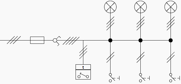
Important Note: We can connect in the circuit (always in parallel way) several lights and as many buttons as we desire.
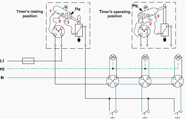
Analytical diagram
Operating mode
Press any button and the coil is activated with the neutral being transferred through that button to the end of the coil. At the other end of the button the phase is applied through the medium contact (2) of the mercurial ampoule and the contact on the right end (3).
Once activated the coil repels the armature (and the whole system) upward. Therefore the mercury bulb changes position shorting out the other two contacts (1) and (2).The phase is transferred to contact (1), namely the luminaires.
The coil is not enabled as long as we let the button and the armature descends due to the weight of the cartridge cavity.
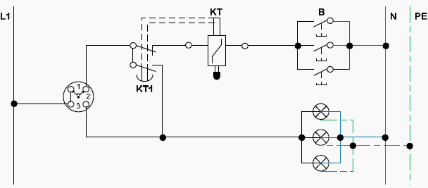
Operating diagram
Obcservations
The automatic staircase timer (ΚΤ), is a combination of an alternative three position switch and a time relay. The positions of the alternative switch are:
- 1st position: For automatic operation
- 2nd position: Permanent discontinuation
- 3rd position: Permanent operation (e.g. when we want to clean the stairway)
Automatic operation
Pressing any instant contact pushbutton (B) , the control circuit closes and the time relay (KT) is stimulated, which subsequently and through the alternative switch closes the power circuit (main circuit), whereby lights illuminate. After a preselected time (as much needed to bring the hydraulic system of the timer in its rest position), power supply of the power circuit is turned off, by opening the contact KT1 of the time relay.
Important note: By observing both the analytical and the operational diagram, we can see that the Neutral (N) is common for the luminaries and the pushbuttons.
2. Lighting circuit controlled by an automatic staircase timer (electronic)
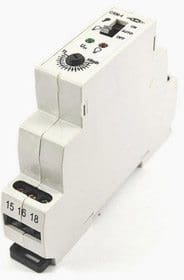
Staircase timers are applied in any residential or commercial building wherever automatic control is required on predefined times.
Lighting control in staircases made with automatic timers (bracket – rail profile), mounted in electrical switchboards at the staircase and activated by pushbuttons with light or no indication located in various places of the staircase or by motion detectors, which detect movements in the range of their surveillance and enable the automatic switch.
2.1 Staircase electronic timer (3 and 4 wire configuration)
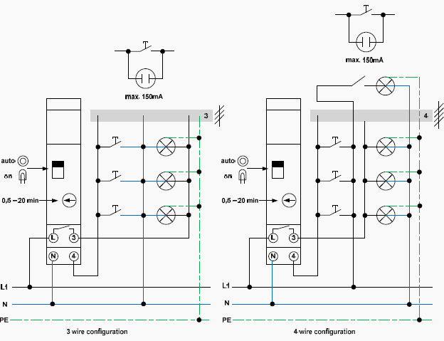
Important Note: One contact of the lights is permanently connected to the Neutral and the other one is connected to the return (for the lights) of the automatic timer.
Operation mode
When you press any button the automatic timer is activated (the Neutral is carried through the button and at his edges 230V voltage is applied) and the main contact closes for as long as we have preselected. At that time the lights will illuminate. The phase is transferred through the main contact of the automatic timer to the other end of the luminaires.
Once this time has elapsed, the contact opens and the lights go out.
Important Note: One contact of the buttons is permanently connected to the Neutral and the other one is connected to the return (for the buttons) of the automatic timer.
2.2 Staircase electronic multifunctional timer (3 and 4 wire configuration)
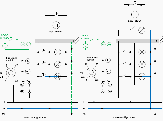
Automatic staircase timers are manufactured for certain lamp wattage.
They have timers so we can choose the interval we want them to be turned on. The multifunctional automatic staircase timers have the option of continuous operation when a button is pressed for more than two seconds and they can increase and decrease their luminance for twenty seconds after the end of regulation time, as a warning that the lights will turn off.
Also, they have the option (changeover switch) to pose the circuit off or keep the lights permanently on.
Some of the automatic multifunctional timers may have separate control input 8 – 240 V AC/DC, galvanic separated (e.g. intercom) and they can also automatically detect the 3 or 4 wire configuration.
Important note:
The automatic staircase timers can be connected with incandescent lamps, halogen lamps, single fluorescent lamps and compact fluorescent electronic lamps.
The electronic staircase automatic timers have some advantages over the older ones.
- Wide range time adjustment.
- Great confidence when they work as there is no fear to get stuck while operating.
- High accuracy of repeatability of the time. Time does not change if no intervening setting.
- Their small size gives them the potential to be installed inside the staircase’s electrical panel.


In the future ….. https://www.facebook.com/photo.php?fbid=418035201553465&set=a.190293597660961.45526.100000409679153&type=1&theater