Introduction To Lighting Circuits
Electrical lines which include lighting circuits begin from the main distribution panel of the installation and each line contains three conductors: phase, neutral and ground. All three conductors reach to the terminal point of each luminaire and if it has a metal chassis the ground should be connected in the appropriate position.
From each main distribution panel at least two lighting supply lines are leaving, so a failure on one line does not sink the entire installation in the dark. Insulation on the conductors must show the colors required by the regulations.
To understand the circuit connections we can use various designs, including the following:
Single line diagram
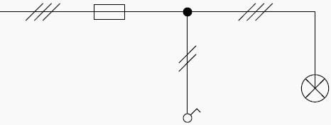
Circuits shown are in the simplified form. These drawings show only the important elements of the lighting circuit and contain information on how to layout, number of the conductors and their cross – section.
Analytical diagram
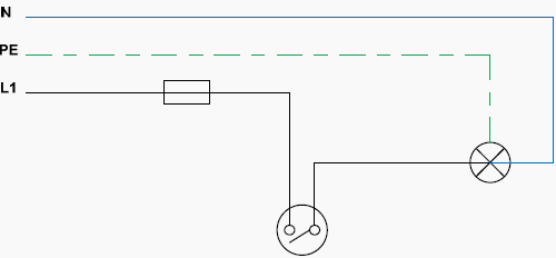
Which show all the lines that connect the different parts of a circuit. These plans in large scale circuits can lose their figuration.
Operating diagram
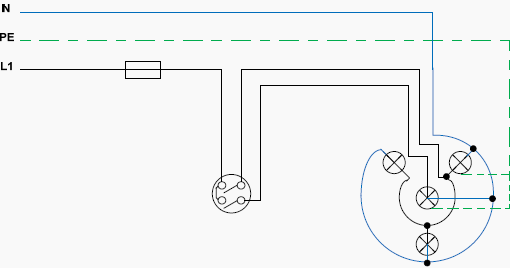
Which show in detail the paths of electrical current. This method of design is descriptive and easy to read.
1. Simply light circuit
Description:
Connection of one or more luminaire points (Lights) controlled by a simple switch. This kind of connection is used in almost all interior electrical installations.
General diagrams
Single line diagram
Analytical diagram
Operating diagram

Important Note:
In all lighting circuits a ground cable must be installed. Usually the luminaires for residential use belong in the next two categories:
- Protection Class I: The device is grounded. The ground wire (yellow / green) must be connected to the clip marked with ground symbol.
- Protection class II: The device is double insulated and cannot be connected to the ground.
2. Selector switch lighting circuit (Comitater)
Description:
A connection of two groups of lamps controlled by a single point. The connection is usually used in chandeliers.
General diagrams
Single line diagram

Analytical diagram
Important Note:
During the design of various electrical circuits we pay attention to draw them in break mode (OFF), unless there are compelling reasons to the contrary. Above the circuit is ‘closed’, feeding all the lights.
Operating diagram

3. Two-way switching lighting circuit (Two extreme switches Aller–Retour)
Description:
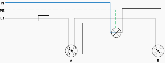
Control of a lighting circuit from two points (A and B). This type of circuit is used in hallways, rooms with two entrances, stairs, bedrooms, e.t.c.
General diagrams
Single line diagram

Analytical diagram
With rotary switches
With pushbutton switches
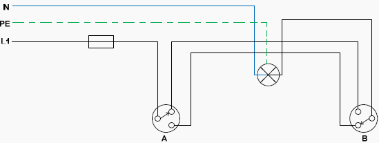
Operating diagram
With rotary switches

With pushbutton switches

4. Switching lighting circuit (Aller–Retour) with two extreme switches and one or more intermediate switches
Description:
Control of a lighting circuit from three or more points. This type of circuit is used in large rooms, long corridors, staircases and generally in large rooms.
General diagrams
Single line diagram

Analytical diagram
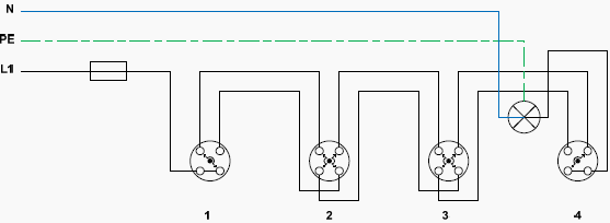
Operating diagram

5. Lighting circuits with fluorescent tubes
Description:
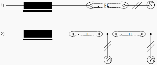
- Circuit of a 40W fluorescent tube, with 40W Ballast and starter.
- Circuit with two fluorescent tubes (20W each), with 40W Ballast and two starters (20W each)
The fluorescent tubes are used particularly in factories, offices, for decoration and advertising or promotion of goods. In recent years fluorescent tubes are used in residential installations.
General diagrams
Single line diagram
Important Note:
In figure b) we can add more fluorescent tubes if we want in series but we should also add more starters and a more powerful ballast.
Analitycal diagrams
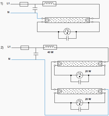
Operating diagrams
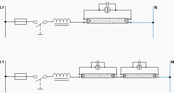
Important Notes:
In figure 2) If one of the two starters or one of the two lamps stop working, then none of the lamps will eventually function.
The metal chassis of the lamp or the ballast’s choke should be grounded. The fluorescent tubes import reactive power to the grid. With new European Union directives, mechanical ballasts are repealed and only electronic ballasts (triac) should be used, which limit the reactive power.
The starter and the capacitor are abolished and we have direct ignition of the lamp.


Where a Can I get to learn the single line diagram
thanks a lot for every one on this site.
thanks for ever for all.
You explained about Lighting Connections well with diagrams so that everyone can catch it easily. And it was a great article. Thanks for sharing it.
Very great effort Edvard, very useful articles in a single click, thanks a lot for sharing with us…
Thank you Alok! For this particulary technical article a big thank goes to Emmanouil :D
It is very usuful side
Hello,
Very usefull website! Can you tell me in what software program the diagrams are made?
Thanks!
Microsoft Visio
Thanks for you valuable efforts.
Useful Site.
I am very happy to join EEP, I have learned a lot. Thanks very much..
I am happy to join the EEP and have to learn alot.
Welcome Sahir! Glad to have in the EEP team!
Excellent overview of lighting connections. Just keep on!!
Best regards
Thanks a lot Edvard…
Dear Emmanouil Angeladas,
Welcome to our EEP family..!!!!
Hello Bipul Raman, i feel great that i belong to EEP. All of your technical articles inspired me to become a contributor.