Protective Mechanisms
IEC 60728-11 complies with the state of the art and offers easy, standardized and effective protective mechanisms against the effects of lightning strikes into antennas.
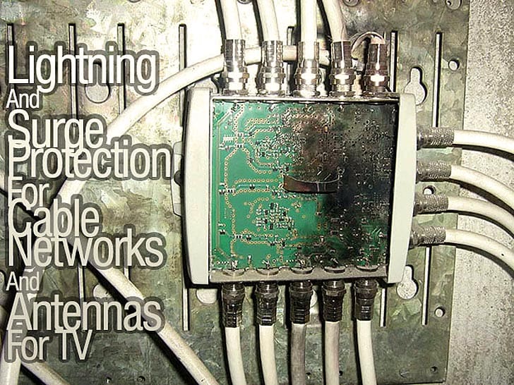
Antennas installed according to this standard do not increase the probability of lightnings to strike the object under consideration. Nor is an antenna system installed according to this standard a substitute for a lightning protection system of a building or structure.
This standard deals with the safety requirements for stationary systems and devices and is, if applicable, also valid for mobile and temporary systems (e.g. campers, recreational vehicles). The range of validity comprises cable TV networks (CATV networks) and satellite community antenna television systems as well as individual receiving networks.
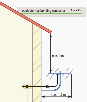
Outside antennas which are installed at a level of more than 2 m below the roofing or the roof-edge and at distance of less than 1.5 m from the building (Figure 1) as well as antenna systems inside a building are excepted from the following measures.
However, at least the connection of the coaxial cable shields to an equipotential bonding conductor is urgently recommended.
Antennas must not be installed on buildings with easily inflammable roofing (e.g. thatch or similar materials). Antenna cables and earthing conductors must not lead through those sections of rooms where easily inflammable materials like hay, straw or alike are stored, or in which there is a potential risk of explosive atmosphere to arise.
An equipotential bonding conductor has to be mechanically solid with a copper cross section of minimum 4 mm2. The shields of the coaxial cables going in or out of the building have to be connected with an equipotential bonding conductor and by the shortest route with a common equipotential bonding bar.
An earthing conductor being capable of carrying lightning current can be a single solid wire having a minimum cross section of 16 mm2 of insulated or bare copper, or of insulated 25 mm2 aluminium or of 50 mm2 aluminium wrought alloy (not to be directly installed on or in plaster nor on or in concrete), or of steel 50 mm2 , preferably for external installation.
- the metal frame of the building or structure,
- the interconnected reinforcement steel of the building or structure,
- facades, railings and substructures of metal facades, provided that
- their dimensions meet the requirements of down-conductor systems and their thickness is not less than 0.5 mm,
- their electrical conductivity in vertical direction is ensured (these permanent connections have to be carried out by brazing, welding, pressing, screwing or riveting), or that the distance between metal structures does not exceed 1 mm and the overlapping of two structural elements is at least 100 cm2.
IEC 62305-3 does no longer stipulate this possibility of overlapping sheet metal, except the substructure is continuously conductive in vertical direction. If not, the overlapping sheet metals have to be safely interconnected according to the requirements of IEC 62305-3.
Attention: Forming of loops has to be avoided.
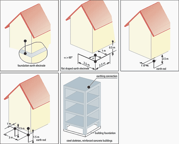
The earth-termination system has to be designed according to one of the following manners (Figure 2):
- Connection with the external lightning protection system of the building or structure.
- Connection with the earth-termination system of the building or structure.
- Connection with at least two horizontal earth electrodes having a minimum length of 2.5 m, being installed in an angle > 60 °, at least 0.5 m deep and not closer than 1 m to the foundation, or connected with one vertical or slanted earth electrode not shorter than 2.5 m or two vertical earth electrodes not shorter than 1.5 m, installed at a distance of 3 m from each other and not closer than 1 m to the foundation.
Natural components such as interconnected reinforcement of concrete or other suitable underground metal constructions embedded into the foundation of the building the dimensions of which complying with the above limit values, can be used as well. Other earth-termination system according to IEC 62305-3 are also permitted.
If a supplementary earth electrode is installed adjacent to the earth termination system of the building, the earth electrodes have to be interconnected.
In case of buildings without lightning protection system (LPS), the mast with an earthing conductor has to be connected by the shortest route with the earth electrode. The earthing conductor has to be installed straightly and vertically. The coaxial cable shields have to be connected with the mast by equipotential bonding conductors (Figure 3).
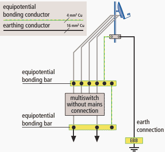
Only if this is not possible, a direct connection with the external lightning protection system shall be implemented. In this case the aris ing partial lightning currents via the coaxial conductors have to be taken into account individually.
Lightning equipotential bonding has to be performed for the conductors going into the building.
To be continued very soon…
Reference: Lightning Protection Guide – DEHN Inc. (dehn.de)




Dear Edvard Csanyi,
Can you tell me, please, for what use is this circuit?
Img1: http://i.imgur.com/Sb1bRJC.jpg
Img2: http://i.imgur.com/l11Pu2y.jpg
Img3: http://i.imgur.com/ZVuh10M.jpg
Thank you!
Celestino
(sorry my english)