
Estimated Study Time: 7 minutes
Nonlinear loads
Nonlinear loads like adjustable frequency controls create line harmonics when connected to the AC power distribution system. These harmonic currents are a result of non-sinusoidal current, which is a characteristic of all adjustable frequency controls using diodes or silicon controlled rectifiers (SCRs) on the input.
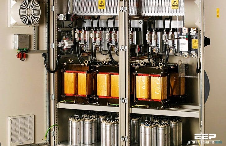 Line harmonic currents created by adjustable frequency control (on photo: 400V real-time passive harmonic filter; via enspecpower.com)
The control’s input current is composed of the fundamental sinusoidal current (50 or 60 Hz) and currents at frequencies higher than the fundamental frequency. These harmonic currents do not aid in the transmission of power to the connected load, but contribute to the volt-ampere losses in the power distribution system.
Some of the negative effects of AC line harmonics if not properly addressed are:
- Possible interference with communication equipment.
- Possible overheating of transformers and other branch circuit equipment.
- Possible increased heating in motors connected across-the-line due to copper and iron losses.
- Possible resonance with power factor capacitors.
The AC input line harmonic current magnitudes may vary with control designs. The power distribution system impedance at the installation and the control’s input design determines the actual magnitude of line harmonic currents. Because of these variables, it is difficult to suggest general guidelines to predict the magnitude of the line harmonic currents. When the actual harmonic current values are required, the control manufacturer should be consulted.
When AC line harmonic currents exist in a power distribution system, the harmonic currents may be amplified through frequency resonance of power factor correction capacitors with transformer inductance to cause equipment failures.
 is the interconnection between two utility customers")
The harmonic voltage and current distortion values at the PCC may be reduced through several abatement methods that include:
1. Design Techniques
Power system design – decreasing the drive system load, as a percentage of the total power distribution network load will improve harmonic voltage distortion conditions.
DC Link choke/inductor – an inherent design feature within some controls, provides a minimum level of harmonic reduction by changing the rate of rise of the input current.
2. Line Impedance
AC line reactor – based upon the percent of line impedance, provides a lower amplitude of harmonic currents by slowing down the rate of rise of input current pulses, similar to DC link choke.
Drive Isolation Transformer – provides similar performance to an AC line reactor with the additional power quality benefit of being able to adjust the voltage magnitude.
3. Multi-pulse methods/converter design topologies
Phase multiplication – involves the use of a phase-shifting transformer for feeding multi-pulse control inputs. By properly shifting the phase relationship to various 6-pulse controls, the net effect in the power system is to create a 12-pulse circuit with cancellation of the 5th and 7th characteristic harmonics. However, this method is most effective when the motor loads are of equal size and load.
12-pulse rectifier – a control that utilizes a dual 6-pulse rectifier network with a phase shifting transformer for proper commutation of the dual bridges. Similar to phase multiplication, the net effect is cancellation of the 5th, 7th, 17th, and 19th characteristic harmonics.

18-pulse rectifier – a control that utilizes three 6-pulse rectifier networks with phase shifting transformers for proper commutation. This results in an improved waveform, cancellation of lower order 5th, 7th, 11th, 13th, 23rd, 25th, 29th, and 31st characteristic harmonics.
Active rectifier input – a control that incorporates gate controlled power semi-conductors in the input rectifier stage to shape the input current waveform, to a sinusoidal current waveform symmetrical to the voltage.
4. Harmonic Filters
Shunt filters – passive filters that are properly designed and for the 5th, 7th, and 13th harmonics can effectively reduce the harmonic currents in a power distribution system. Each filter consists of a series LC circuit, tuned to resonate at a specific harmonic frequency acting as a low impedance path shunting the source of harmonics.

Specific site application considerations apply since the filter cannot distinguish between the harmonics from the control equipment, other external power system harmonics, or additional installed control equipment.
Series filters – these filters consist of a parallel LC circuit tuned to resonate a specific frequency, similar to a shunt filter. The series reactor acts to de-tune other power distribution system harmonics from being trapped by the passive filter.
Harmonic injection – adaptive compensators are designed to constantly monitor the AC line input current to the control by injecting a current equal in frequency/magnitude and 180° out phase to the distorted current. This action will cause cancellation of the line harmonic currents.
Active filters – designed primarily for multiple non-linear harmonic loads, monitoring dynamic load conditions and switching necessary VAR compensation.
Harmonics: What are they, why do I care, how do I solve?
Reference: NEMA Standards Publication – Application Guide For AC Adjustable Speed Drive Systems
Related electrical guides & articles


Edvard Csanyi
Hi, I'm an electrical engineer, programmer and founder of EEP - Electrical Engineering Portal. I worked twelve years at Schneider Electric in the position of technical support for low- and medium-voltage projects and the design of busbar trunking systems.I'm highly specialized in the design of LV/MV switchgear and low-voltage, high-power busbar trunking (<6300A) in substations, commercial buildings and industry facilities. I'm also a professional in AutoCAD programming.
Profile: Edvard Csanyi

Good
i am looking for harmonic filter panel
we are providing harmonic filters for industries active type for various type of industries such as engineering and non-engineering commercial establishments IT sector etc.,
we provide total solutions and are reachable at 09444420696