
Estimated Study Time: 7 minutes
Locking and safety reasons
In all cases the choice of locks and safety positions requires prior analysis of the locking sequence to be applied in order to correctly define the requirement and clearly identify the related risks. Remember that “electric” locking systems are never considered to be adequate.
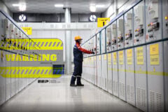
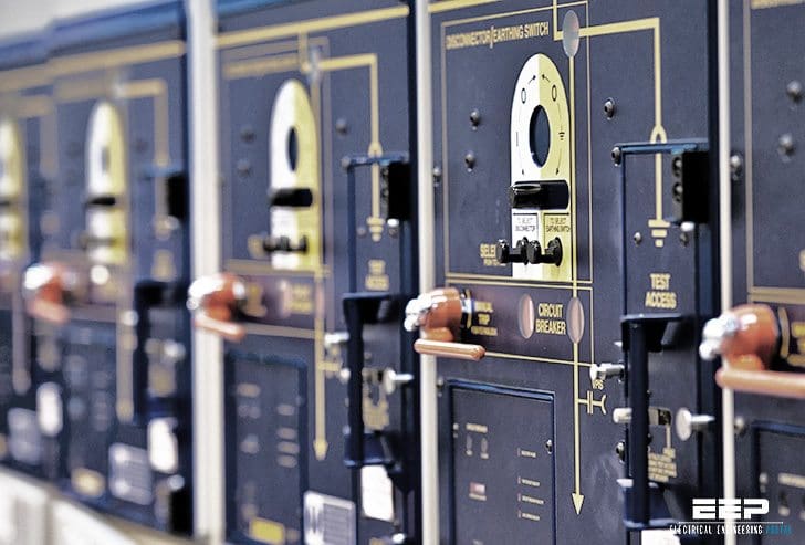 5 good examples of locking out HV/MV/LV structures and equipment (photo credit: mardix.com)
In principle, only “mechanical” locking systems are capable of ensuring safety (as long as they themselves are reliable).
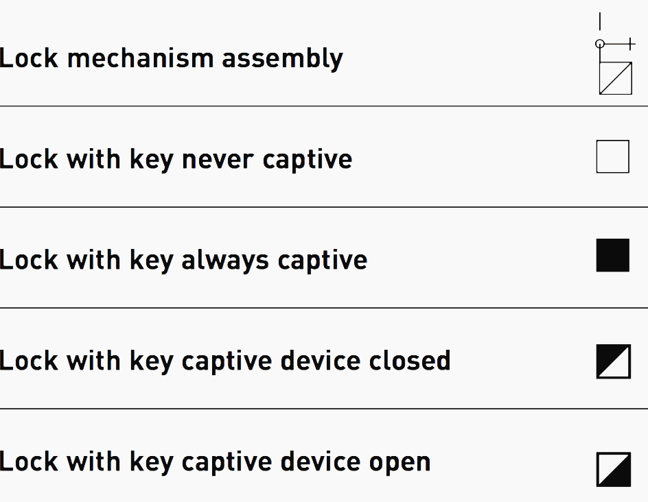
Diagrammatic symbols are also used, but it is advisable to explain complex sequences in words. However, first let’s see the symbols we will use in locking diagram and then five different locking examples:
- Locking between earthing switch, HV switch and cell door
- Locking cells on HV loop system
- Locking on supply inversion and on HV station
- HV/TR/LV locking (functional symbols)
- Locking on LV supply inversion
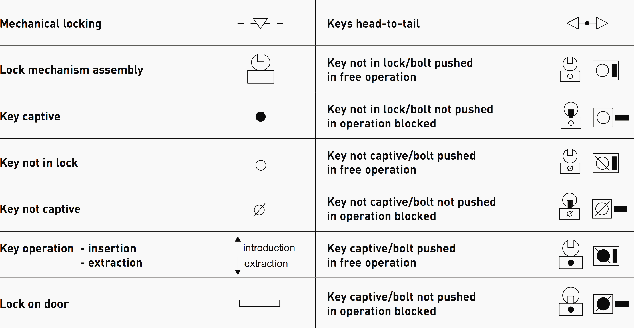
Example of diagrammatic symbols
Functional locking symbols
Locking examples
#1 – Locking between earthing switch, HV switch and cell door
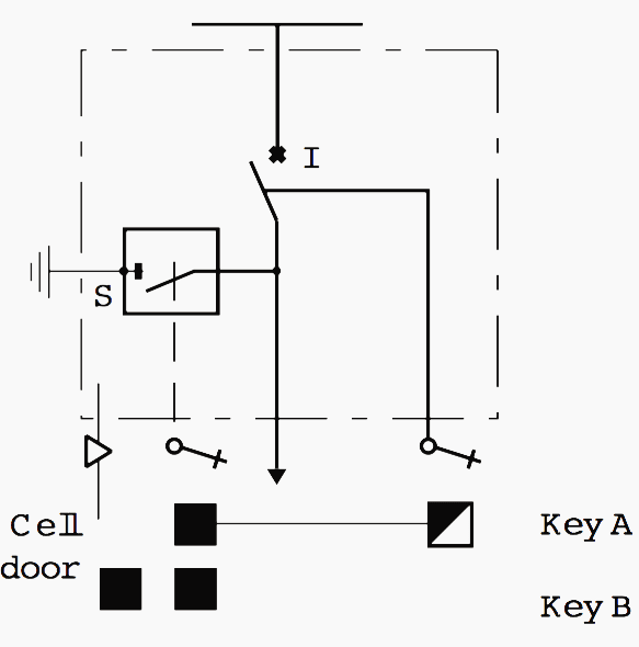
Locking sequence:
- Opening of switch I.
- The key is released.
- Transfer of key a to isolating switch S.
- Closing of isolating switch S.
- Key B is released.
- Opening of the cell door with key B.
- Key B remains captive.
#2 – Locking cells on HV loop system
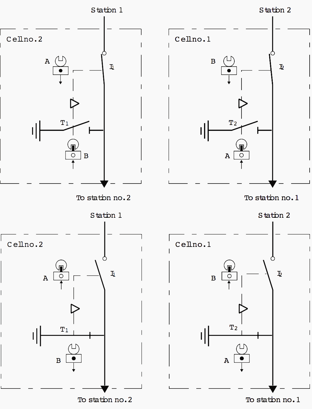
The purpose of this procedure is to prevent the earthing switches closing when the cell is supplied upstream or downstream (loop-back).
NB: Switches I and isolating switches T are designed to be mechanically controlled.
Immobilisation sequence:
- Opening of switch I1.
- Immobilisation of switch I1 and release of key A.
- Opening of switch I2.
- Immobilisation of switch I2 and release of key B.
- Unlocking of earthing switch T2 with key A.
- Closing of earthing switch T2.
- Key A is captive.
- Unlocking of earthing switch T1 with key B.
- Closing of earthing switch T1.
- Key B is captive.
#3 – Locking on supply inversion and on HV station
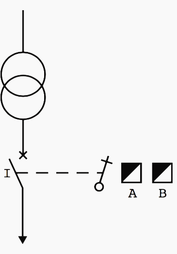
The draw-out circuit breaker is fitted with two locks. In normal operation, the circuit breaker I is closed, and keys A and B are captive. Opening the circuit breaker releases keys A and B. key a is transferred to the HV cell upstream (see example 2). Key B is transferred to the standby supply (see example 4).
#4 – HV/TR/LV locking (functional symbols)
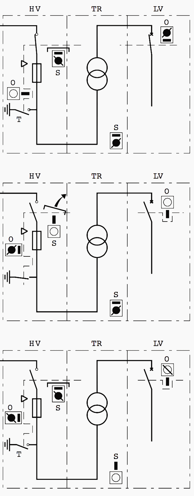
Used in supply stations with LV metering, this sequence, which is one of the most common, is used to access the terminals of the transformer after:
- Opening and locking of the LV circuit breaker.
- Opening and locking of the HV cell.
- Earthing of the separate HV supply.
Service state:
- The LV circuit breaker is closed.
- Key O is captive.
- The HV cell is closed.
- Key S is captive.
- The transformer terminals are not accessible.
Locking sequence:
- Opening and drawing out of the LV circuit breaker.
- Key O is released.
- Transfer of key O to the lock on the HV cell.
- Opening of the HV switch and closing of the earthing switch by mechanical control. Operation is possible by key transfer, as in example 1.
- Key O becomes captive.
- The cell panel can be opened.
- Key S can be removed.
- Unlocking of the immobilisation cover of the plug-in terminals.
- Key S becomes captive.
#5 – Locking on LV supply inversion
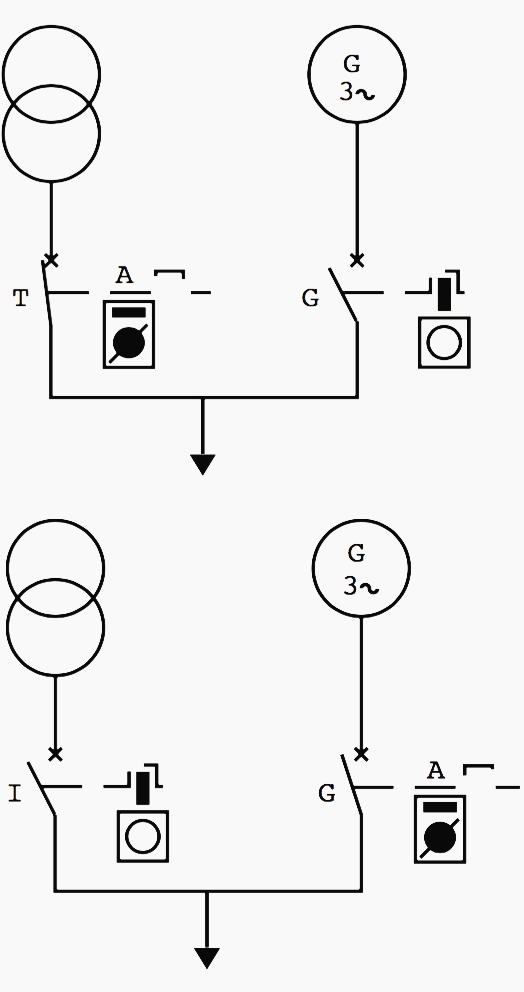
A standby power supply must only be coupled on an installation when it is certain that the main power supply is disconnected.
In normal operation:
- Supply via transformer.
- Circuit breaker I is closed.
- Key A is captive.
In standby operation:
- Circuit breaker I is open.
- The associated lock is unlocked and key A is released.
- Key A is transferred to the lock on circuit breaker G, which is closed.
- Key A is captive.
Instruction video Switching ON cable earthing
Instruction video Switching OFF cable earthing
Reference // Power book; Operation functions by Legrand
Related electrical guides & articles


Edvard Csanyi
Hi, I'm an electrical engineer, programmer and founder of EEP - Electrical Engineering Portal. I worked twelve years at Schneider Electric in the position of technical support for low- and medium-voltage projects and the design of busbar trunking systems.I'm highly specialized in the design of LV/MV switchgear and low-voltage, high-power busbar trunking (<6300A) in substations, commercial buildings and industry facilities. I'm also a professional in AutoCAD programming.
Profile: Edvard Csanyi

Does exist any solution for remote locking between two distant cells? Optical fiber or other ?