
Estimated Study Time: 20 minutes
The art of lockout in control circuitry
Lockouts and auto-reclosures are apprentices of power systems protection that have long served to regulate power supply and safeguard important components from probable catastrophes. But are we taking them seriously enough? In implementing the lockout features, apart from their placements in control circuitry, operating principles, construction, and functionalities remain almost the same over decades, while their counterparts have seen massive overhauls.
 Lockout relay (master trip relay) in substation protection and control design
This article will focus on the practical applications of lockout relays on mainstream switchgear and protection. The primary goal is to discuss the transition from the current mode of application to possible upgrades and adaptations in modern digital power substation protection.
The terminologies lockout relay, master trip relay, and 86-relay are used interchangeably in this article.
- What does lockout relay do exactly?
- Operation in protection circuit
- What makes lockout relay indispensable in substation protection
- An analogy with auto-reclosure
- Next-generation implementation of lockout features
1. What does lockout relay do exactly?
Protection relays are undoubtedly the soul of substation protection and require multiple auxiliary relays to support them for the overall functionality of protection, control, and monitoring. Master trip relay or lockout relay, also known by ANSI code 86, holds a significant position as an intermediator between the protection relay and control points, even though it is not self-equipped with fault sensing capabilities.
The master trip relay can operate as a hub of multiple protection relays trip commands and drive multiple subsequent contacts. This makes the relay a protagonist to execute simultaneous commands like breaker trips, interlocks, alarms, data display, SCADA extensions, and lockouts.
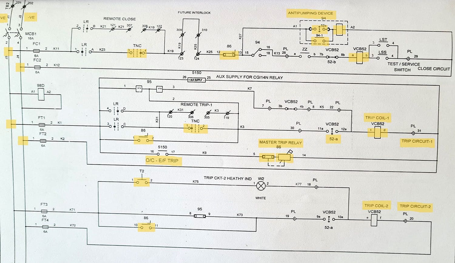
Figure 1 – Trip function interface: Soft Logic to a hard-wired connection
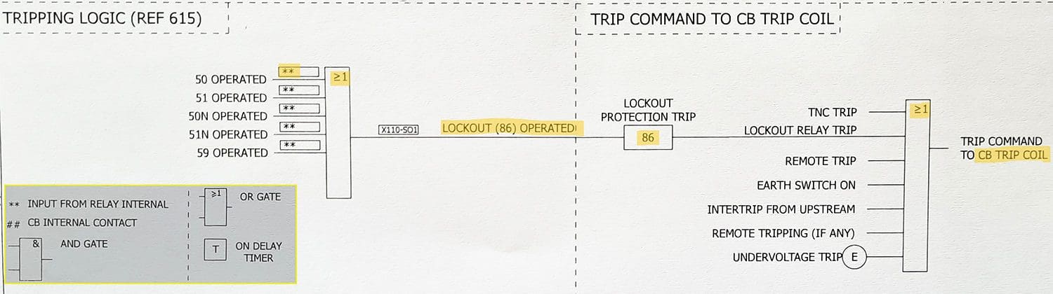
In absence of a master trip relay, imagine connecting individual trip circuits of each protection relay to circuit breaker trip coils. Along with the obvious extra cost incurred, this would be a mess for operation and troubleshooting. The concept of lockout relay as an intermediator of protection is illustrated in Figure 1.
Initiation of fault signals in modern-day protection IED activates the lockout relay to perform the trip command of associated breakers. Likewise, the command for a closing coil of breaker only receives the close signal upon confirmation from the lockout relay.
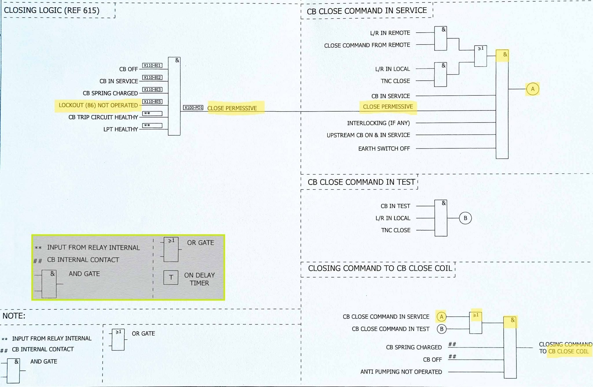
The sequence of operation for medium voltage switchgear with numerical protection relay to execute closing command is illustrated in Figure 2.
Figure 2 – Close function interface- Soft Logic to a hard-wired connection (click to zoom)
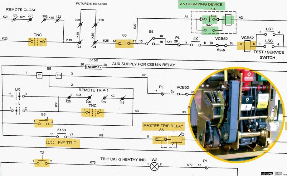
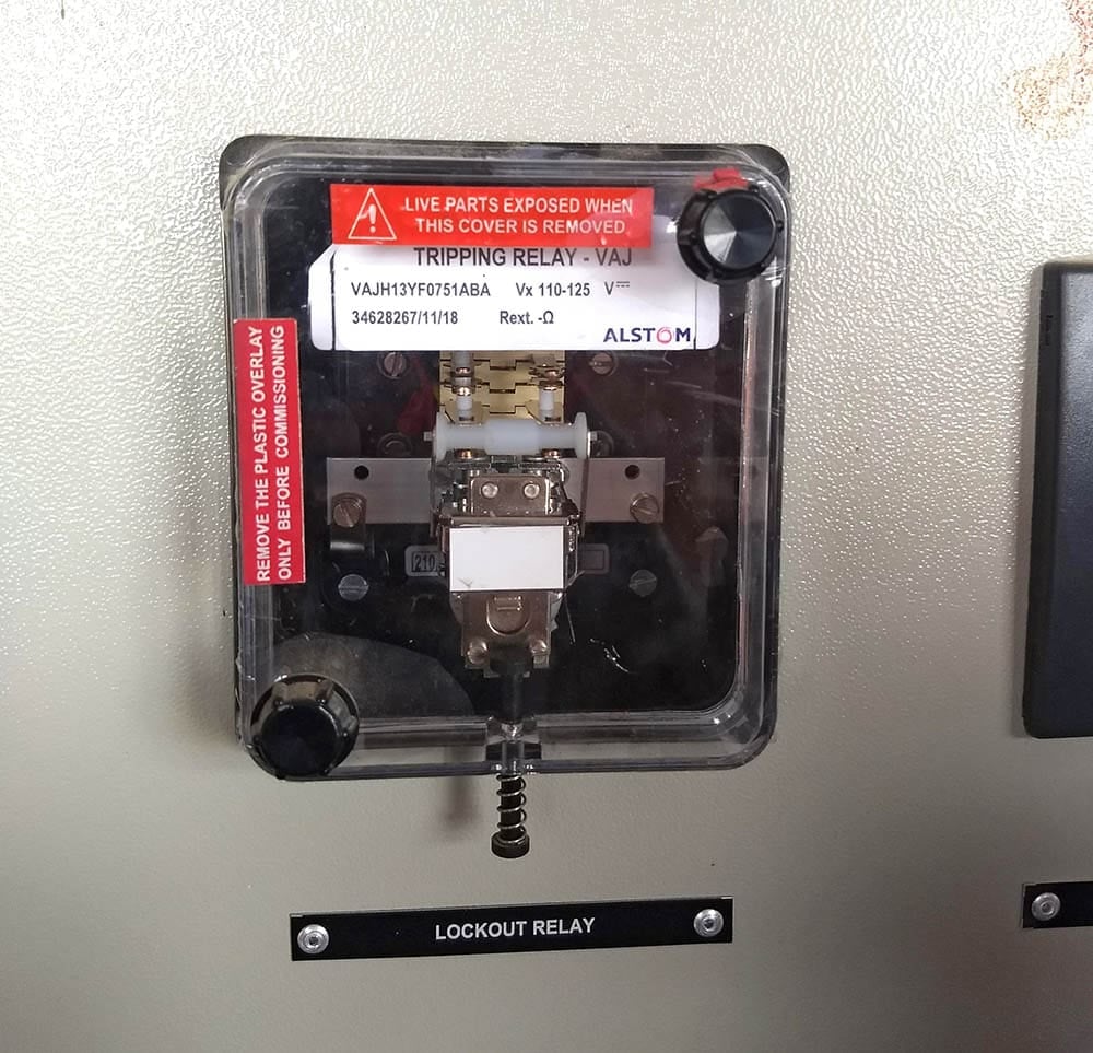
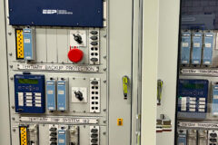
The picture in Figure 3 is of one of the most popular choices for master trip relay with a hinged flag reset mechanism used in a plethora of applications like medium voltage radial feeder protection, transformer protection, busbar protection, etc. The movable part with a white cover is used for indicating two states of the relay- Faulty or normal.
The legacy master trip relays rely on solenoid operating coils for their operations, and the terminals are latched every time the lockout command activates. This mandatorily requires resetting (Self, via flags or push buttons, or electrically via pickup voltage) of latched terminals to resume the circuit for normal operation.
This holds more importance in relatively less sophisticated substations as it requires the operators to manually acknowledge and take necessary action for fault remedial before closing back the circuit.
Figure 3 – Lockout relay in an MV breaker panel
Electromechanical master trip relays provide excellent isolation against any probable trip circuit hazards that might damage the costly set of modern-day microprocessor-based protection relays that are vulnerable to voltage spikes and transients in trip circuits.
The hinged armature construction with adequate electrical and mechanical rating ensures prompt and continuous rated operation within a fraction of seconds without over-heating.
Go back to the Contents Table ↑
2. Operation in protection circuit
The master trip relays usually consist of operating coil rated at 220V or 110V DC and supplied with a continuous negative DC voltage from one end. It operates to latch the contacts once it receives positive voltage from the opposite end, which is triggered by operating of protective relay associated.
In trip circuits, this completes the path to extend positive voltage at the trip coil, and the breaker operates to open the contact, along with 52-a secondary contacts.
Figure 4 – Vacuum circuit breaker (VCB) trip and close coil operation (click to zoom)
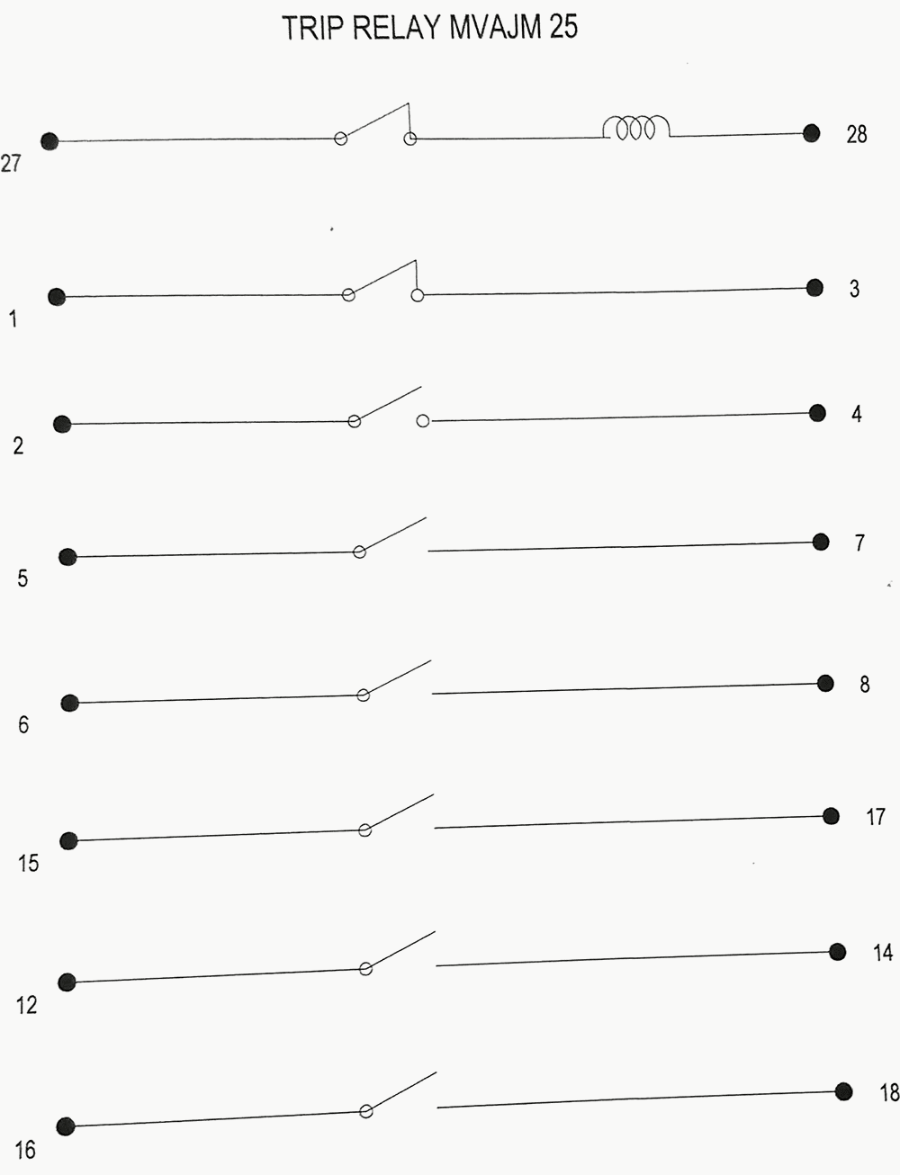
Meanwhile, the contact multiplications of master trip relay help to cover up ancillary duties of annunciation led indication, and so on. As it stands, the breaker can be closed back neither automatically nor manually via TNC switch unless the latched terminal NC contact 12-13 is reverted by resetting the operating coil of the master trip relay.
The figure below is a contact multiplication for a master trip relay. Between 27-28 terminals lies the operating coil of the relay in a series of its own NC contact, which helps to automatically cut off the supply to the coil once it is triggered.
Figure 5 – Contact multiplication principle of master trip relay
Anti-pumping relay is another essential component in circuit breaking, which helps to avoid any possibility of CB hunting effect due to spring failure in TNC switch. It forms a part of the closing circuit as its auxiliary NC contact links the path of positive voltage extension to the breaker closing coil, and its operating coil forms a parallel path to ensure the closing coil does not receive continuous positive voltage.
Related electrical guides & articles


Bishal Lamichhane
Electrical Engineer (B.E Electrical, M. Sc Engineering) with specialization in energy systems planning. Actively involved in design and supervision of LV/MV substations, power supply augmentations and electrification for utilities and bulk consumers like airports and commercial entities. An enthusiast and scholar of power systems analysis.Profile: Bishal Lamichhane
