
Estimated Study Time: 15 minutes
The purpose of LV protection unit
If we are talking about LV applications, the protection (or trip) unit is a functional part of a circuit breaker. In most cases, they are physically integrated into the same housing as well. To better explain the purpose of the protection unit, let us first remember what a circuit breaker does.
 How does low voltage protection unit work
A circuit breaker is a device that, as the name implies, serves to safely break the circuit while current flows through it. This circuit breaker operation can be initiated for two different reasons:
- The electrical operator (or some other person) wants to switch off some circuit. This usually happens while the actual current is smaller than the rated current of the circuit.
- Some fault downstream of the circuit breaker occurs. In this case, the actual current (or voltage) will be outside rated limits for the circuit, and the circuit breaker will disconnect it from the supply, in order to prevent damage to the equipment and safety risk.
In other cases listed above, operation of the circuit breaker will be initiated without the intervention of any external factor or device, including an electrician, or some other technical personnel.
So, how does a circuit breaker “know” that currently exceeds some permissible value, and therefore may be potentially dangerous, because of which it needs to be interrupted?
That is exactly the purpose of the protection unit. This piece of hardware needs to sense electrical disturbance (usually current rise), detect the necessity for interruption by comparing actual and permissible value, and act on other circuit breaker’s parts in order to open poles and break the circuit within adequate time.
Again, if the actual current after closing exceeds the permissible value, the protection unit will trip immediately after.
It is very important to understand that “permissible value” doesn’t necessarily be a unique and exact number. In most cases, overcurrent magnitude and duration are related, and both of them have an influence on the decision whether the protection unit will trip or not. More details about this will be discussed later.
Of course, if we want the circuit breaker to perform all tasks properly, it has to be specified in accordance with starting currents and fault currents relevant for the point of installation.
Every major technical characteristic of the circuit breaker must comply with corresponding voltage and current value of the circuit.
Protection functions
The protection function is basically a constraint that needs to be followed by some electrical quantity (voltage or current) in order for the circuit breaker to remain closed. If this constraint is breached, a circuit breaker will trip.
Basic protection functions, which are covered by all protection units, are overload and “instantaneous” short circuit protection. The presence of all other functions depends on the type and complexity of the protection unit.
1. Overload protection (L)
The area of this function is marked with the letter L in Figure 2. For LV applications, it is always the inverse type of curve. That means greater the current – shorter the tripping time, and vice versa.
This function has a major influence on the thermal protection of the equipment, and it is relevant for the coordination of circuit breaker and cable carrying capacity. It can be adjusted at a value smaller than the rated current of the circuit breaker.
For example, a 1600 A rated circuit breaker can trip the actual current of 800 A after some time, only if overload protection is adjusted for such purpose.
2. Instantaneous short circuit protection (I)
As the name implies, the purpose of this protection is to be activated in the case of a short circuit. It is marked with letter I in Figure 2. It usually covers the area from the value which is several times larger than the rated current of the circuit breaker, up to his breaking capacity.
A lower threshold of this function shall be in accordance (greater than) with starting current of the protected circuit.
This function is called “instantaneous” because tripping time is very short (up to three periods or shorter). This tripping cannot be delayed, it depends on the circuit breaker’s construction, and it is also called reflex tripping.
3. Time-delayed short circuit protection (S)
Also called selective short circuit protection, which is why it is marked with the letter S in Figure 2 above. Unlike instantaneous short protection, this function can be time delayed. In that way, downstream circuit breaker closer to fault location, with a shorter time delay or instantaneous protection activated, will have enough time to clear the fault before the upstream circuit breaker opens. That is how selectivity may be achieved.
For some protection units, the delay time may be chosen to be fixed, or inversely dependent on current (dashed line in Figure 2).
4. Earth fault protection (G)
Earth (or ground) fault is marked with the letter G in Figure 2. This curve is compared to the actual value of residual current, which is measured by the external current transformer, or calculated as the vector sum of three-phase currents.
It is very useful, or even mandatory, for LV networks where efficient protection against indirect contact cannot be achieved by overcurrent devices, i.e. functions, which is most often the case in networks with TT earthing arrangement.
5. Advanced protection functions
Modern electronic protection units may be equipped with various other protection functions, and some of them are:
- Overvoltage and Undervoltage protection
- Overfrequency and Underfrequency protection
- Residual voltage protection
- Phase unbalance protection
- Overtemperature protection (see Figure 7)
Protection unit types
Based on the operation principle, two types of LV protection units can be defined: thermomagnetic and electronic. Like circuit breakers, both types can be used for three-pole or four pole protection.
1. Thermomagnetic protection unit
These units serve for basic protection. They can be found mostly inside moulded case circuit breakers, with current ratings of up to 1000 A. Physical appearance of the thermomagnetic protection unit can be seen in Figure 8.
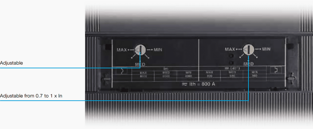
Inside protection units of this type, only overload and instantaneous short circuit protection functions are embedded. The first one is realized by the thermal device based on bimetallic element, and the second is realized by a magnetic device with a working principle based on the correlation between the current flowing through the circuit breaker and the magnetic force produced by that current.
Overload trip threshold is usually in the range of (0.7 – 1) In, while short circuit threshold is typically in the range of (2–12) In, where In represents rated current of the circuit breaker. Interface for parameter adjustment is usually in the form of rotating knobs.
Related electrical guides & articles


Miodrag Kokotovic
Graduated from Faculty of Electrical Engineering, within University of Belgrade, in the field of electrical power systems. Expert in electrical part of tender preparation, design, procurement, construction and commissioning of treatment plants and pumping stations, electrical power quality and energy management.Profile: Miodrag Kokotovic
