H.T. Drives
Cane Mill Drive
Consider the application of a drive to a cane milling unit where the speed is to be variable from full to half rated speed. The drive is to be capable of producing full rated torque over the entire speed range. The suitability of the LV VFD drive will be considered and vary the speed of full throttle torque/speed characteristics of the average mill drive turbine.
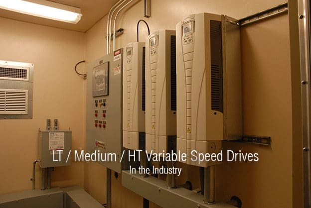
Continued from first part: LT / Medium / HT VFD Used In the Industry (part 1)
A very desirable feature is the increasing torque with decreasing speed.
Most mill drives are called upon, from time to time, to handle transient overloads. When this occur while the turbine is running at rated speed and under full throttle, it will be incapable of supplying the extra torque unless it slows down.
This state of affairs would, in all probability, be unacceptable and can only overcome by installing an over-size turbine. It is interesting to note that the installed turbine horsepower of most installations is twice that which is required to mill the rated quantity of fiber. Cane mills are invariably run at speeds other than their rated full speed and it is under these conditions that the turbine suffers its greatest drawback. Reference to the steam consumption at constant torque and variable speed, the horsepower at constant torque is proportional to speed.
The turbine is basically a constant speed device and if it is called upon to operate at a speed other than that for which it is designed, its efficiency drops and it becomes an uneconomical prime mover.
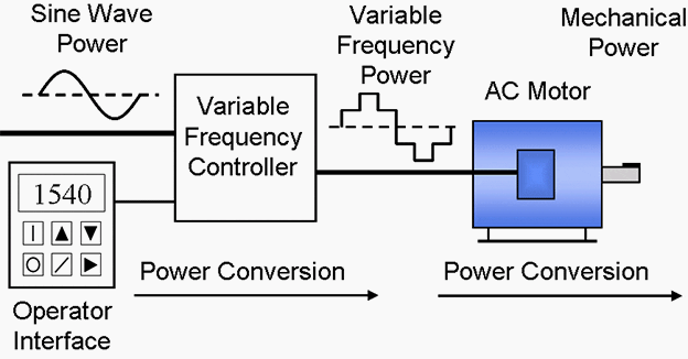
AC Motor
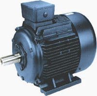
The AC electric motor used in a VFD system is usually a three-phase induction motor. Some types of single-phase motors can be used, but three-phase motors are usually preferred. Various types of synchronous motors offer advantages in some situations, but three phase induction motors are suitable for more purposes and are generally the most economical choice.
Motors that are designed for fixed-speed operation are often used. Elevated voltage stresses imposed on induction motors that are supplied by VFDs require that such motors be designed for definite-purpose inverter-fed duty in accordance to such requirements as Part 31 of NEMA Standard MG-1.
Variable Frequency Drives and Harmonic Abatement Techniques
Several techniques can be used to mitigate harmonics.
The most commons are:
- Line Reactors – Passive Filters
- DC Chokes – Active Filters
- Multi Pulse drives
- 12 Pulse Drives
- 18 Pulse Drives
Line Reactors
Three phase line reactors added in series with a VFD will reduce harmonics. This is a relatively inexpensive solution and can lower harmonics by 50% depending on the amount of impedance added to the line.
DC Chokes
Instead of placing line reactors in series with the VFD, a DC choke can be added to the drive’s DC bus reducing approximately the same amount of harmonics as the AC reactor. The advantage of DC chokes is they are smaller in size and are often mounted inside the VFD.
Multi Pulse Drives
12 and 18 pulse drives are alternative solutions to reduce harmonics. In 12 pulse drives, the 5th and 7th harmonics are theoretically non-existent. Similarly, an 18 pulse drive only injects the 17th harmonic and higher to the line. To achieve the multiple pulse effect, additional converter bridges and phase shifting transformers are used making the solution expensive and increasing panel size.
Passive Filters
Passive filters consist of static components like inductors, capacitors, and resistors arranged in predetermined fashion to either attenuate the flow of harmonic currents through them or to shunt the harmonic component into them.
There are several types of passive filters but the most effective is the low pass broadband filter, which offers great performance and versatility with low risk of resonance with the line.
Active Filters and Front Ends
Most passive techniques aim to cure the harmonic problems once they have been created. Active filters, or active front ends, use dynamic switches like IGBTs and other power components to stop harmonics from occurring in the first place. Current flow through a switch is manipulated to recreate a waveform that linearly follows the applied voltage waveform.
Apart from the active front ends, there also exist active shunt filters that introduce a current waveform into the distribution network that when combined with the harmonic current cancels the later and results in an almost perfect sinusoidal waveform.
The disadvantage of these solutions is still their cost.
Comparison of HT VFD and LT VFD
| Sl.No | Specification | HT VFD | LT VFD | Approx. Power Loss with LT VFD Full load |
| 1 | Input Step-Down transformer | Not required as 54 pulse input built in panel | 11000 / 690V 12 Pulse transformer required at input | 2-3% |
| 2 | Output choke requirement | Not required due to multi level technology, output waveforms sine wave | Required due to PWM waveform causing higher motor temperature | 1% |
| 3 | Harmonic Filter | Not required as the generated harmonics are less than 3% THD due to 54 pulse input rectification | Harmonics are generated approximately 10% THD in 12 pulse, hence AHF required to reduce further harmonic level | 1-2% |
| 4 | Input power factor | More than 0.96 at anyloading | Real power factor is very low approx. 0.75 at less loading | 0.2% |
| 5 | Motor temperature / Noise | Low temperature and noise even at less speed due to Sine Wave output | Higher temperature and noise due to PWM Wave at output | >0.2% |
| 6 | Cable cost andpower losses (Heat Losses in cable) | Less current (61 amp),hence less size, cost and power losses | Higher current (61 amp),hence high size, cost and power losses | <0.5% |
| 7 | AC requirement | Less heat loss, so AC capacity required less, which cause less power consumption | More heat loss, so AC capacity required high, which cause large power consumption | <1% |
| 8 | Starting LT | We can Run in bypass mode as starting current in bypass is less | Bypass start is not possible due to very high current requirement as rated current higher | – |
Conclusion
Presently, the Sugar Milling plant is driven by using LT-VFD Drives of 690 Volts. As such the Co-Gen sugar plant generating 11KV system voltage, the 11KV VFD drives can be used in the place LT – VFD Drives. If we are using 11 KV VFD drives THD will be reduced considerably to 1.5%.
In cost implication, 11 KV VFD Drive will be around 5% more than the LT Drives units. An attempt can be made in Co-gen sugar plants using 11KV VFD drives system in the milling plant and avoid step down Transformers.





Dear Sir,
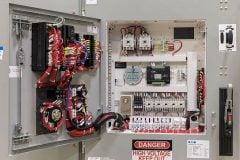
MV SNUBBER RESISTOR ASSEMBLY /MFR : ALLEN BRADLEY/TYPY: 81001-956-53-R – These resistors are for VFD – 250 A.
He was damaged, as is evident in the attached picture.
The customer needs the same resistors or a similar replacement in stock.
This VFD controls its MV motor power 2150 KW / 6.6 KV/716 rpm/10 poles.
Below are the cat no for the materials you had requested.
Quantity 1 of 81001-959-57-R (6 DEVICE POWER CAGE ASSY). This includes Heatsinks, snubber resistors, snubber caps and sharing resistors as per MV components.
Quantity 6 of 81001-340-71-R (PKG-ASSY SCR,COPPER & SPGDB).
Quantity 1 of 81000-620-51-R (CLAMP ASSY 11KN).
Quantity 1 of 81002-517-51-R (POINT LOAD CLAMP PLATE ASSY).
BR
Hani – JOIES
sir plase give me vfd losses in ht pumping motors
motors kw 700
The advantages of HT VFDs over LT VFDs are quite appealing……but how can HT VFD be an alternative if the driven motors installed are of such capacity for which HT voltage levels are impractical?? Or in other words how can LTmotors be driven by HT VFDs….
May be a foolish question but would surely like to know!!!
Hi sir
I am electrical engineering student
Studying in LNCT bhopal.
Please sir give some advice to become successful engineer.
Please sir