
Estimated Study Time: 19 minutes
The danger of earth potential rise
During the passage of earth-fault current a substation earth electrode is subjected to an earth potential rise. Potential gradients develop in the surrounding ground area and these are highest adjacent to the substation earth electrode. The earth potential rise reduces to approximately zero (or true earth potential) at some distance from the substation earth electrode.
 Arrangements for LV supply into high earth potential rise substation
A person could be at risk if they can simultaneously contact parts at different potential; thus in a well-designed system, the potential differences between metallic items will be kept to safe levels regardless of the earth potential rise.
Ground potential gradients around the electrode system, if great enough, can present a hazard to persons and so effective measures to limit them should be incorporated in the design.
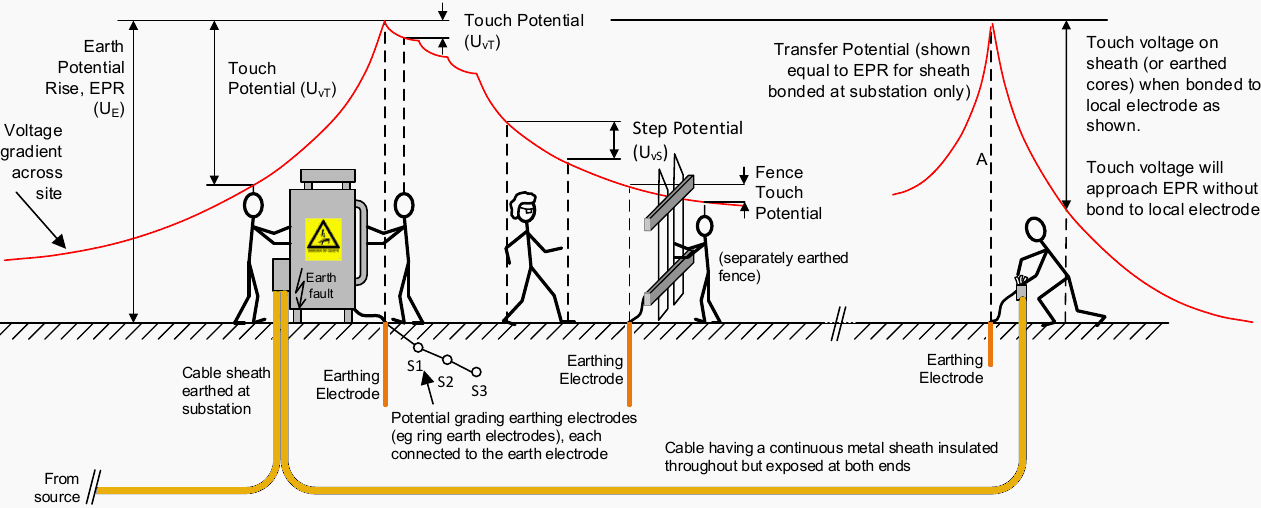
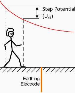
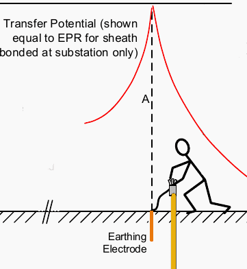
The three main design parameters relate to touch, step and transfer potentials as defined below. These terms are shown as UvT , UvS and A respectively in Figure 1.
Figure 1 – Touch, step and transfer potentials resulting from an earth fault (click to zoom)
- Touch potential
- Step potential
- Transfer potential
- LV installations near high potential rise sites
- Network supplies to/from high potential rise sites
- LV supply into high earth potential rise site
- Arrangements for LV supply into high earth potential rise site:
- BONUS (PDF) 🔗 Download Switchgear Handbook
1. Touch potential
“Touch potential” term describes the voltage appearing between a person’s hands and feet, or between a person’s hands. Hand to foot touch potential arises from the fact that the earth potential rise at a person’s feet can be somewhat lower in value than that present on the buried earth electrode (and any connected metalwork). See Figure 1.
If an earthed metallic structure is accessible, a person standing on the ground 1 m away and touching the structure will be subject to the touch potential. In addition, the permissible limits for step potential are usually much higher than for touch potential.
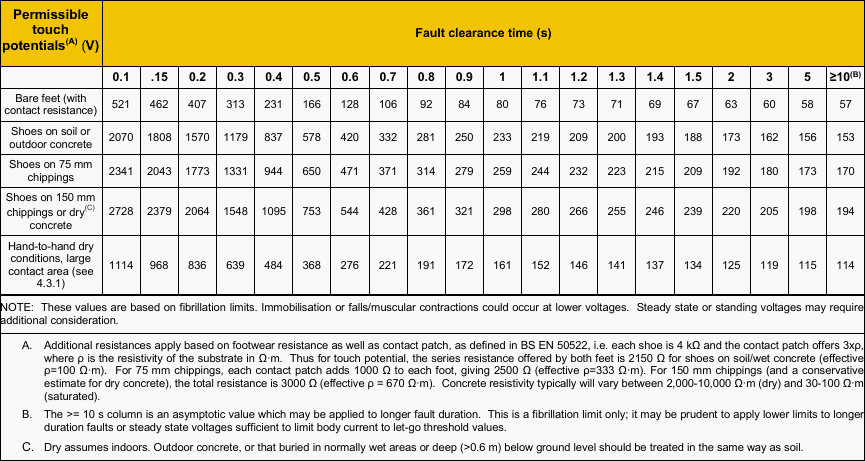
In some situations, the hand-to-hand touch potential should be considered, for example if unbonded parts are within 2 m. The permissible limits for this scenario can be calculated as described in IEC 60479-1, using the body impedance not exceeded by 5 % of the population.
Typical values for dry conditions and large contact area are shown in Table 1.
Table 1 – Permissible touch potentials for typical fault clearance times (click to zoom)
In general, such situations should be designed out, e.g. by increasing separation or introducing barriers if the systems should be electrically separate, or by bonding items together.
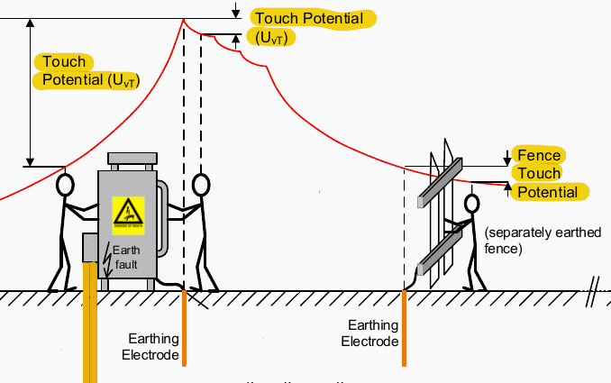
The siting of fences needs consideration in this regard.
Figure 2 – Touch potential
2. Step potential
The potential gradient in the ground is greatest immediately adjacent to the substation earth electrode area. Accordingly, the maximum step potential at a time of substation potential rise will be experienced by a person who has one foot on the ground of maximum potential rise and the other foot one step towards true earth.
For purposes of assessment the step distance is taken as one metre. See Figure 3.
Figure 3 – Step potential
3. Transfer potential
A metallic object having length – a fence, a pipe, a cable sheath or a cable core, for example, may be located so as to bring in (import) or carry out (export) a potential to or from the site. By such means a remote, or true earth (zero) potential can be transferred into an area of high earth potential rise or vice-versa.
For example, a long wire fence tied to a (bonded) substation fence could export the site earth potential rise to the end of the wire fence, where it may pose an electric shock hazard to somebody standing on soil at true earth potential.
The limits for permissible transfer potential relate to shock risk (touch and step potential), and equipment damage / insulation breakdown (withstand voltage).
Figure 4 – Transfer potential
4. LV installations near high potential rise sites
LV electrodes (segregated systems) should be clear of the relevant voltage contour. The consideration also applies to any customer’s TT system earth electrode. If necessary the electrode(s) should be relocated or the shape of the high potential rise zone altered by careful positioning of HV electrodes.
In addition, where possible, LV electrode locations should place them clear of any fallen HV or EHV conductors.
The siting of LV earths should consider zones with elevated potential e.g. some properties close to high potential rise substations or EHV towers may themselves be in an area of high potential rise, in which case provision of an LV earth derived from outside that zone may introduce a touch potential risk at the installation, due to the LV earth being a remote earth reference.
Detailed modelling of HV/LV networks may demonstrate that potential differences are not significant, due to the influence of the network on the shape of the contours; however, such modelling may not be practicable. If any doubt exists, customers should not be offered an earth terminal, and no LV network earths should be located in the area of high potential rise.
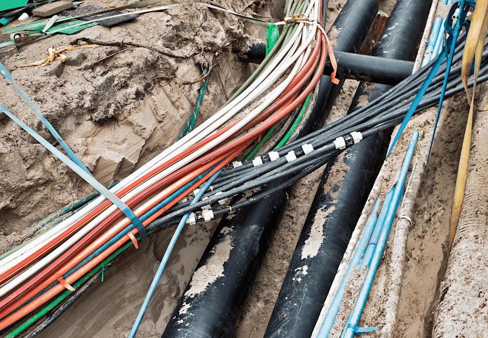
Cables passing through the area should be ducted or otherwise insulated to limit stress voltage to permissible limits. Typically a customer will use their own TT system earth electrode; however if properties are in an area where earth potential rise exceeds 1200 V, it is possible that they will experience L-E or N-E insulation failures under HV or EHV fault conditions and isolation transformers or careful siting of HV/LV transformers and electrode systems may be required.
Figure 5 – Low voltage and high voltage cables laid in a trench in substation
5. Network supplies to/from high potential rise sites
Network supplies into high potential rise sites invariably need care if the network earth is to remain segregated from the high potential rise site earth. In remaining separate, this can introduce touch potential risk within the site. It is normally necessary to use a careful combination of bonding and segregation to ensure that danger does not arise within the site, or on the wider network.
Sheath breaks, insulated glands or unearthed overhead line sections are often convenient mechanisms to segregate the earthing systems.
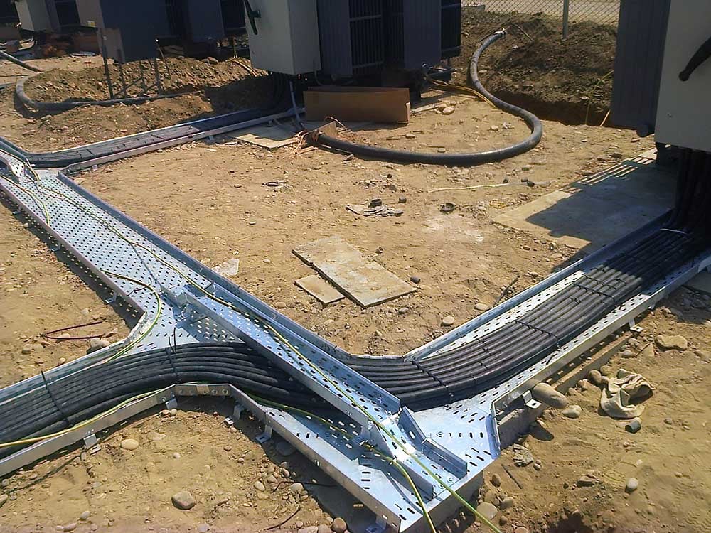
It may be necessary to apply ducting or additional insulation to prevent insulation breakdown and resultant fault current diversion from the high potential rise site into the wider network.
Figure 6 – Substation ducts with power cables and grounding cables
6. LV supply into high earth potential rise site
This case study considers the provision of an LV supply into a transmission substation with an earth potential rise which cannot safely be carried outside the substation boundary (i.e.the earth potential rise exceeds 2× safe step and touch potential thresholds).
The following parameters apply:
| Earth Potential Rise | 3 kV |
| Protection Clearance Time | 0.2 seconds |
Scenario: The substation is in a suburban location with a local underground LV network and mixed overhead / underground 11 kV cable system. The LV network supplies nearby properties and remains outside the HOT zone (650 V) which is calculated to extend 150 m from the site. A 100 A, 3-phase LV supply has been requested by the substation operator, to provide a backup to local site supply transformers.
The earth potential rise exceeds that which can safely be imposed on the LV network under fault conditions. Therefore, taking a standard LV supply into the site from the nearby network is not an option as the LV neutral/earth would invariably become combined with the substation earthing.
The available options, and the advantages/disadvantages of each, are below.
7. Arrangements for LV supply into high earth potential rise site
7.1 Arrangement #1
11 kV cable to local transformer located in the transmission substation
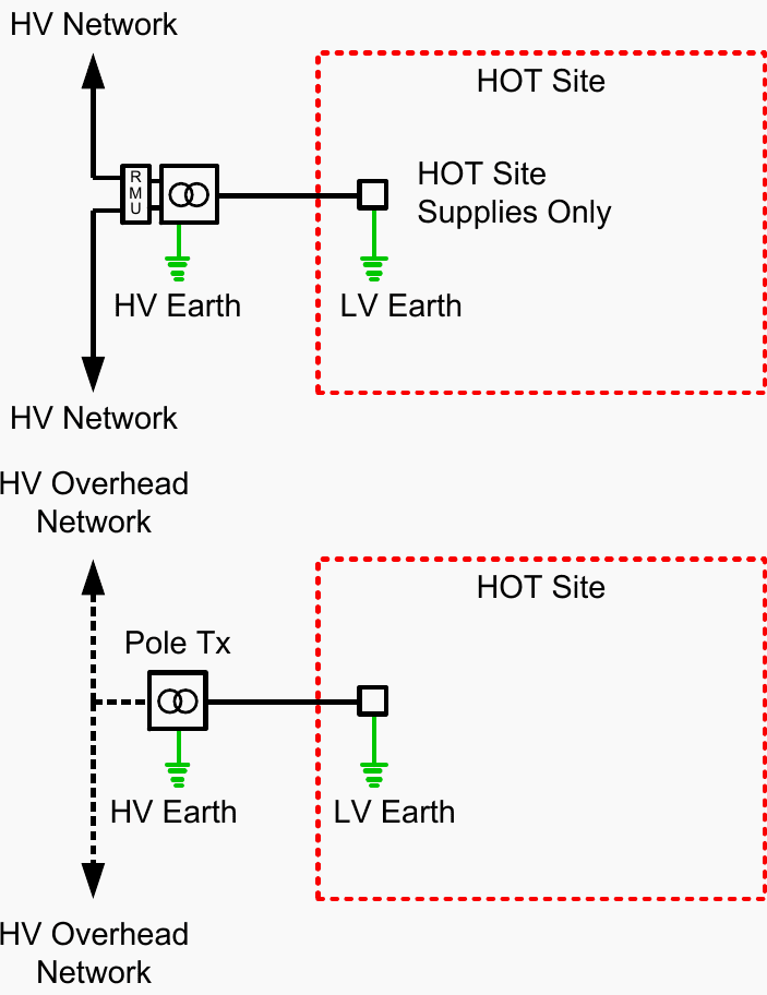
Figure 7 – 11 kV cable to local transformer located in the transmission substation
The 11 kV system can be assumed to be remotely earthed and may therefore adopt a close-to-zero-potential rise under transmission earth potential rise events. If the cable is taken into the site, its sheath insulation could puncture and a high earth potential rise could be exported to the 11 kV system.
To avoid this, the cable should be ducted within the highest voltage contours (dependent on its sheath withstand voltage). Extending ducting to the 2 kV contour is a relatively common practice to avoid this. Any such cable connection into a HOT site requires extreme care with the earthing of the switchgear/transformer, as the earthing systems for the 11 kV cable should not be combined with site earths.
However, this can cause:
- Touch potentials between cable sheath and local steelwork,
- No metallic return for 11 kV faults beyond the break, requiring the substation earth to be able to limit 11 kV earth potential rise and of sufficiently low resistance to operate 11 kV protection, and
- Operational issues if the switchgear earth is applied, since the 11 kV cable cores will become connected to the local site earth. This could create a hazard for staff working on the cable or elsewhere on the 11 kV network unless specific operational practices are adopted.
Further Study – Electrical safety hazards awareness (with realistic work scenarios)
Electrical safety hazards awareness (with realistic work scenarios)
7.2 Arrangement #2
11 kV overhead line supply to transmission substation with a pole-mounted or ground-mounted transformer
Figure 8 – 11 kV overhead line supply to transmission substation with a pole-mounted or ground-mounted transformer
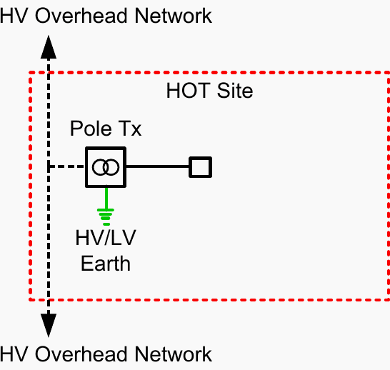
An 11 kV supply to the substation, if via 3-wire (unearthed) overhead construction, is a simple and effective solution to the issues described above. The overhead line can effectively be carried direct into the site, where it can supply a ground-mounted or pole-mounted transformer.
For both arrangements, the transformer HV and LV earths can be combined and connected to the site earth. A 3 kV earth potential rise on the site earth is unlikely to initiate flashover between the 11 kV phases and steelwork, or between any short 11 kV cable sheath-to-cores, although this possibility should be considered in extreme earth potential rise situations.
The disadvantage of this method is that the supply may be more vulnerable than underground supplies and consequently might be unacceptable where a highly resilient supply is necessary.
7.3 Arrangement #3
LV supply from network transmission substation
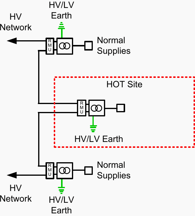
Figure 9 – LV supply from network transmission substation
As previously stated, it is not possible to take a standard LV supply, as there is a real risk that the high earth potential rise could be transferred to other customers. Similarly, providing an LV supply without an earth terminal (i.e. TT arrangement) also poses a significant risk of insulation breakdown / flashover to the LV system during transmission earth potential rise events as the LV neutral/earth will remain at close-to-zero volts.
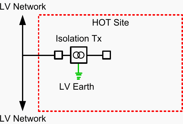
An LV supply may be provided via an isolation transformer, though care is required with the siting and protection of the isolating unit itself.
7.4 Arrangement #4
Dedicated off-site transformer and LV supply into transmission substation
Figure 10 – Dedicated off-site transformer and LV supply into transmission substation
A dedicated off-site transformer offers no benefit over the previous solutions, and introduces the risk of exporting transmission earth potential rise to the transformer.
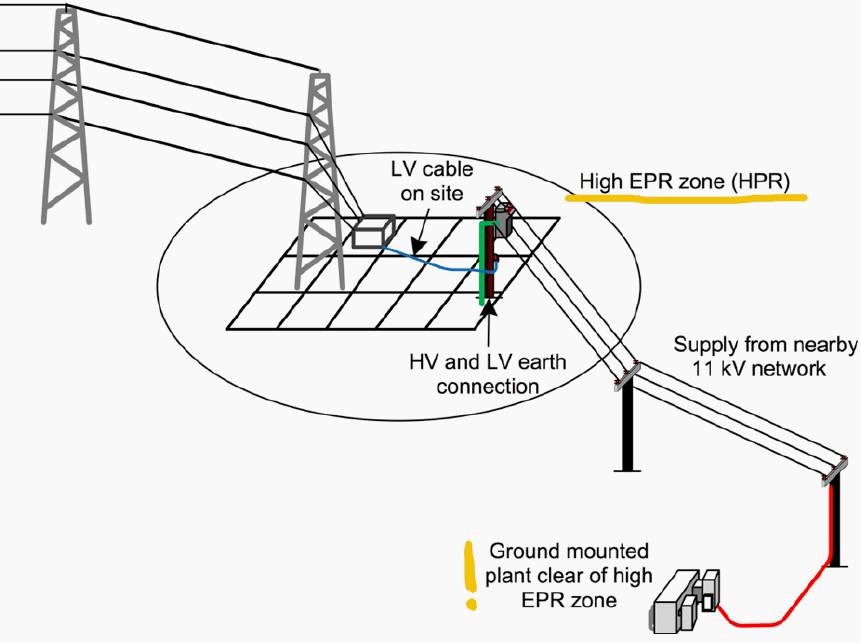
The pole-mounted transformer and overhead 11 kV line solution (see Figure 11) has been adopted as it is the minimum cost solution and (because it is a back-up supply) the reliability is acceptable to the transmission network operator. For operational reasons, an ABSD is best located outside the site boundary and will serve as a point of isolation and earthing point for the 11 kV network beyond that point.
Figure 11 – Overhead supply into high earth potential rise site site
7. BONUS (PDF): Download Switchgear Handbook
Download Guide: Switchgear Handbook (for premium members only):
Reference: Guidelines for the design, installation, testing and maintenance of main earthing systems in substations
Related electrical guides & articles


Edvard Csanyi
Hi, I'm an electrical engineer, programmer and founder of EEP - Electrical Engineering Portal. I worked twelve years at Schneider Electric in the position of technical support for low- and medium-voltage projects and the design of busbar trunking systems.I'm highly specialized in the design of LV/MV switchgear and low-voltage, high-power busbar trunking (<6300A) in substations, commercial buildings and industry facilities. I'm also a professional in AutoCAD programming.
Profile: Edvard Csanyi

Well done Edvard. Appreciate if we take contact
Thanks!!