
Estimated Study Time: 12 minutes
Magnetic voltage transformers
Magnetic voltage transformers are used to provide a secondary signal that is proportional to the actual prevailing primary value. These signals are used to supply measuring instruments, meters, relays and other similar apparatuses.
 Working principle and connections of magnetic voltage transformers (photo credit: ABB)
The primary values measured are system currents and voltages. The secondary signal available has to fulfill the following criteria:
- Standardized nominal value
- Minimum ratio and phase displacement errors
- Capability to supply the power needed by the secondary protection and measurement devices
- Necessary insulation level against the primary circuits
- Predictable performance under primary system normal conditions and specially under abnormal conditions
The primary winding is affected by the actual network voltage at every instant of time. This primary voltage value is then converted to a secondary voltage value based on the rated voltage-transforming ratio of the voltage transformer.
In certain applications, the connection between phases (double-pole) is also used. The third variant would be a three-phase unit where the three-phase units are in one physical enclosure and the phases are star-connected against earth.
Like with the current transformers, a number of separate secondary cores are used for measuring and protection purposes. It is also possible to use one core for both measuring and protection.
Figure 1 – Representation of a single-pole (on the left) voltage transformer with two secondary cores and a double-pole (on the right) with one secondary core
Unlike with current transformers, the voltage transformers normally cater for one fixed transforming ratio, and special designs with double transforming ratios can be employed based on the individual application needs.
The most common type of a voltage transformer on the distribution side is a set of three single-pole ones having two separate cores, namely the star-connected one for measuring purposes and the broken-delta-connected one for residual voltage measurement.
Figure 2 – A set of three single-pole VTs having two secondary cores
The secondary circuits of a voltage transformer have to be protected with fuses or miniature circuit breakers. These protection devices should be mounted as close to the voltage transformers as possible.
If there is a load resistor connected to the open-delta core of the voltage transformer for damping oscillation caused by the ferroresonance phenomenon, the resistor has to be connected to the voltage transformer side of the secondary circuit protection device.
The ferroresonance phenomenon is due to the resonance circuit formed by the single-pole VT inductance to earth and the unearthed system capacitance to earth. This resonance circuit can cause oscillations resulting in heating, and finally damaging, the voltage transformers. To damp down these oscillations, a load resistor is connected across the open-delta winding.
These problems are most likely to occur in un- earthed systems with minimum feeder length connected.
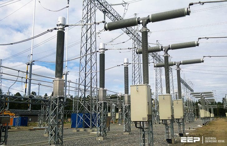
Figure 3 – A 66 kV oil-insulated outdoor-type one-pole magnetic voltage transformer

Where:
- Primary terminal
- Oil level sight glass
- Oil
- Quartz filling
- Insulator
- Lifting lug
- Secondary terminal box
- Neutral and terminal
- Expansion system
- Paper insulation
- Tank
- Primary winding
- Ground connection
Figure 4 – A 12 kV indoor epoxy resin-cased one-pole magnetic voltage transformer

Where:
- Medium voltage terminals
- Primary coil
- Magnetic circuit
- Secondary winding
- Epoxy body
- Secondary outlets
- Base plate
- Cover of secondary terminals used for outlet sealing
- Nameplate
With an ideal voltage transformer, the ratio between the primary and secondary voltage always equals the ratio between the primary and secondary winding turns.

The behavior of voltage transformers and the conformities to basic electrical laws can be demonstrated by the use of equivalent circuit shown below.

From the above equivalent circuit, it can be seen that with a non-ideal transformer there are always some errors included in the measurement. These errors are mainly caused by the excitation current (Io) and the load current (I2), which introduces both ratio errors and angle errors between the reduced primary voltage and the actual secondary voltage.
The issue is approached through an example. It is assumed here that a three-phase set of one-pole voltage transformer, having the below shown data labels, is used for energy measurement and residual overvoltage protection.
Example of reading voltage transformer data
Let’a take a look this example of VT:
- 6600:√3/100: √3/100:3V
- a – n 30VA cl.0.5
- da – dn 100VA cl.6P 50Hz 400VA
- 7.2/20/60kV
- 1.9xUn 8h
6600:√3/100: √3/100:3V
These values determine the rated voltage ratio. The voltage transformer is a single-pole one intended for phase-to-ground voltage measurement. The rated primary voltage is 6600:√3V and the rated secondary voltages are 100:√3V and 100:3V.
Under full (fault impedance is zero) earth fault situation in unearthed systems, the measured value from open-delta connection would be approximately 100V.
a – n 30VA cl.0.5
The marking a – n 30VA cl.0.5 is the detailed data for the first secondary core intended for measurement. The rated secondary burden is 30VA and the accuracy class is 0.5.
The markings “a” and “n” refer to the secondary terminal markings on the voltage transformer secondary connection box. To comply with the stated accuracy class, the voltage transformer has to fulfill certain requirements regarding voltage and phase displacement errors as shown below.
These limits apply to the secondary burdens between 25-100% of the rated burden.

da – dn 100VA cl.6P
The marking da – dn 100VA cl.6P is the detailed data for the second secondary core intended for protection. The rated secondary burden is100 VA and the accuracy class is 6P.
These limits apply to the secondary burdens between 25-100% of the rated burden. If the open-delta-connected secondary protection winding is used only for ferroresonance damping resistor, it does not have to comply with accuracy requirements.
Accuracy requirements of the voltage transformers’ protection classes
| Protection class | Voltage error ±% | Phase displacement ±min. |
| 3P | 3.0 | 120 |
| 6P | 6.0 | 240 |
50Hz 400VA
Voltage transformers’ rated frequency is (50 Hz). The stated thermal-limiting output is 400 VA. This refers to an apparent power value at the rated secondary voltage that can be taken from a secondary winding under rated primary voltage conditions, without exceeding the limit of temperature rise (classes specified by the standard).
In this condition, the limits of error may be exceeded. If the voltage transformer has more than one secondary winding, this value is to be given separately, as an addition to the secondary core’s specific data.
7.2/20/60 kV
7.2 kV is the highest voltage for the equipment (RMS value). 20 kV is the rated power frequency withstanding voltage (rms test value). 60 kV is the rated lightning impulse withstanding voltage (peak test value).
1.9xUn 8h
The rated voltage factor (1.9) is the multiple of rated primary voltage to determine the maximum voltage at which the transformer must comply with the relevant thermal requirements and the stated accuracy requirements for a specified (8 h) rated time. The voltage factor is determined by the maximum operating voltage in a specific system.
The maximum operating voltage is on the other hand affected by the voltage transformers’ primary winding connections and system earthing conditions.
The following table demonstrates the dependencies.

Reference // Distribution Automation Handbook – Elements of power distribution systems by ABB
Related electrical guides & articles


Edvard Csanyi
Hi, I'm an electrical engineer, programmer and founder of EEP - Electrical Engineering Portal. I worked twelve years at Schneider Electric in the position of technical support for low- and medium-voltage projects and the design of busbar trunking systems.I'm highly specialized in the design of LV/MV switchgear and low-voltage, high-power busbar trunking (<6300A) in substations, commercial buildings and industry facilities. I'm also a professional in AutoCAD programming.
Profile: Edvard Csanyi

Hi, Sir, I would like to use da dn connection to star connection with Earth to get 33.3 Volt in 11000/√3:/110/√3:110:3 potential transformer, is it impossible or not? Because protection circuit is 30 V DC.
Can you guide the schematic idea of this type of voltage transformer 11000/r3/110/r3/110/r3
Thankyou
This is a usual subject but it is well explained congratulion to you!
Thank you Jose!