Low reliability requirement situations
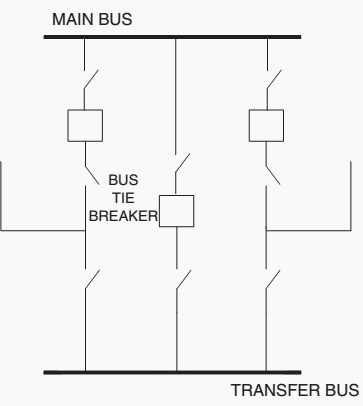
The main and transfer bus configuration connects all circuits between the main bus and a transfer bus (sometimes referred to as an inspection bus). Some arrangements include a bus tie breaker and others simply utilize switches for the tie between the two buses.

This configuration is similar to the single bus arrangement; in that during normal operations, all circuits are connected to the main bus.
So the operating reliability is low; a main bus fault will de-energize all circuits.

However, the transfer bus is used to improve the maintenance process by moving the line of the circuit breaker to be maintained to the transfer bus. Some systems are operated with the transfer bus normally de-energized. When a circuit breaker needs to be maintained, the transfer bus is energized through the tie breaker.
Then the switch, nearest the transfer bus, on the circuit to be maintained is closed and its breaker and associated isolation switches are opened. Thus transferring the line of the circuit breaker to be maintained to the bus tie breaker and avoiding interruption to the circuit load.
1st option
The first option is by transferring the circuit to be maintained to one of the remaining circuits by closing that circuit’s switch (nearest to the transfer bus) and carrying both circuit loads on the one breaker.
This arrangement most likely will require special relay settings for the circuit breaker to carry the transferred load.
2nd option
The second option is by transferring the circuit to be maintained directly to the main bus with no relay protection from the substation. Obviously in the latter arrangement, relay protection (recloser or fuse) immediately outside the substation should be considered to minimizefaults on the maintained line circuit from causing extensive station outages.
The cost of the main and transfer bus arrangement is more than the single bus arrangement because of the added transfer bus and switching devices. In addition, if a low-profile configuration is used, land requirements are substantially more.
Connections of lines to the station should not be very complicated. If a bus tie breaker is not installed, consideration as to normal line loading is important for transfers during maintenance. If lines are normally operated at or close to their capability, loads will need to be transferred or temporary generators provided similar to the single bus arrangement maintenance scenario.
The main and transfer bus arrangement is an initial stage configuration, since a single main bus failure can cause an outage of the entire station.
As load levels at the station rise, consideration of a main bus tie breaker should be made to minimize the amount of load dropped for a single contingency.
Another operational capability of this configuration is that the main bus can be taken out-of-service without an outage to the circuits by supplying from the transfer bus, but obviously, relay protection (recloser or fuse) immediately outside the substation should be considered to minimize faults on any of the line circuit from causing station outages.
Switching operation
- First close the isolators at both side of the bus coupler breaker.
- Then close the bypass isolator of the feeder which is to be transferred to transfer bus.
- Now energized the transfer bus by dosing the bus coupler circuit breaker from remote.
- After bus coupler breaker is closed, now the power from main bus flows to the feeder line through its main breaker as well as bus coupler breaker viatransfer bus.
- Now if main breaker of the feeder is switched off, total power flow will instantaneously shift to the bus coupler breaker and hence this breaker will serve the purpose of protection for the feeder.
- At last the operating personnel open the isolators at both sides of the main circuit breaker to make it isolated from rest of the live system.
References:
- Air-Insulated Substations — Bus Switching Configurations / Michael J. Bio
- Substation layout and accessories and busbar arrangement – Amit Kumar, Nejamul Hoque and Hemendra Kumar Rajput


Very good articles, much informative
Very good help
Thank you very much for all your efforts and valuable info.
Very useful info..
Very Good & usefull Articlefor me & everyone