
Estimated Study Time: 23 minutes
Circuit diagrams & graphic symbols
This technical article will try to shed some light on the main and auxiliary circuit diagrams of switching three-phase motors via contactor and switching directly. We’ll cover some fundamental schematics with an old-school explanations and logics on how they work. But before we dive into diagrams, let’s say some words about the graphic symbols, circuit diagrams in general, their types and some rules.
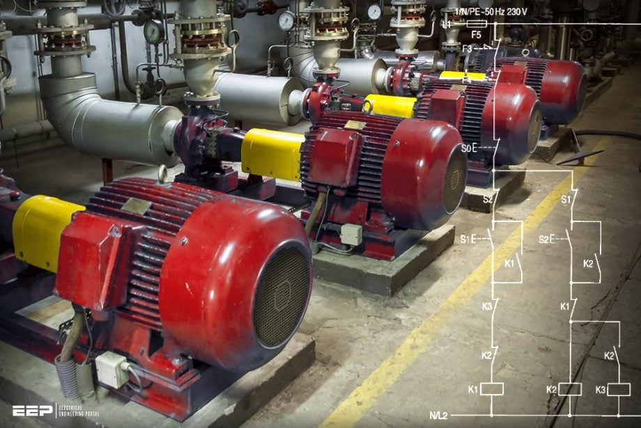 Main and auxiliary circuit diagrams of switching three-phase motors via contactor and directly
In general, the graphic symbols in circuit diagrams are represented in a de-energized and mechanical non-operated state. Deviations from this rule mu be clearly indicated in the circuit diagrams. The different types of diagrams can be classified follows: survey diagram, circuit diagram, and equivalent circuit diagram.
A survey diagram (also known as an overview a block diagram) is a simplified representation of a circuit and shows only the most essential parts. It shows the principle of operation and the structure of the electrical installation (Figure 1).
A circuit diagram is a detailed representation of a circuit with its individual components. It illustrates the principle of operation of the electrical equipment.
Nowadays, the circuit diagram is the most frequently used representation of a circuit in the field of electrical engineering.
Figure 1 – Survey (block) diagram

A circuit diagram is broken down into the main circuit and the auxiliary circuit (control circuit and signalling circuit).
The various circuits are represented separately from left to right in this sequence (Figure 2). The equipment designations are not only used to identify the complete devices themselves, but also to identify all the used contacts and terminals of each device in the circuit. Thus, for example, all the contacts of a particular item of switchgear used in the various current paths are labelled with the same equipment designation.
An equivalent circuit diagram is a special version of an explanatory circuit diagram and serves the analysis and calculation of circuit characteristics.
Figure 2 – Circuit diagram with main and auxiliary circuit
Fundamental circuit diagrams
The following fundamental circuit diagrams illustrate the most commonly used main and auxiliary circuits. They may be considered as generic diagrams and it should be noted that they give no indication of the actual physical location of the devices in the installation.
The auxiliary contacts of an overload relay protecting a particular motor are connected in the common supply circuit for the magnet coils of all the contactors associated with the motor.
This prevents the motor from being switched on too soon via another contactor after the overload relay has tripped.
1. Switching via contactors
The contactor is one of the most important switching devices in industrial circuits. It comprises all the functions which are virtually always required in control systems:
- Remote operation,
- High switching capacity and continuous rating,
- Long mechanical service life,
- Low space requirements,
- Reliable contact making, and
- Complete maintenance-free operation.
In order to fulfill these tasks properly, the contactor requires: clear command signals and observation of the coil voltage tolerances.
The contactor coils are connected either to the voltage between the phase and neutral conductors, or they are connected between two phases at the secondary side of a control voltage transformer in which case the second phase is preferably linked to the protective earth conductor.
Control circuits connected via a control voltage transformer may also be operated without earth connection if they are provided with all insulation monitoring device.
Contactors which must not be energized simultaneously are interlocked via their auxiliary NC contacts. The control switches are interlocked via NC contacts to enable the immediate change-over from one switching state to another without actuation of the OFF pushbutton. Moreover, this interlocking arrangement prevents energizing commands from being given to several contactors at the same time (double commands).
The graphic symbols used in the fundamental circuit diagrams are derived from DIN EN 60617-2.
Suggested Reading – Contactor As An Important Part Of The Motor Control Gear
Go back to the Contents Table ↑
1.1 Contactors with drop-out delay unit for fluttering command signals
Fluttering command signals may lead to chattering of the contactor and may cause the destruction of the magnet system or may lead to welding of the contacts when high currents are being switched.
When using, for example, Siemens contactors, a voltage tolerance of 0.8 to 1.1×Us must be observed. If the rated control supply voltage is too high, the service life will be reduced and it may even lead to burning-out of the coil. If the rated control voltage is too low, the contact pressure may be too low, which can cause contact welding.
Contactors equipped with a drop-out delay (off-delay) unit prevent the damaging effects due to ambiguous and or fluttering command signals. Figure 3 illustrates an auxiliary circuit diagram of a contactor control with a drop-out delay unit.
Figure 3 – Circuit diagram for auxiliary circuit using a drop-out delay unit

Required auxiliary contacts:
- Contactor K3 with 2NO and d.c. economy circuit,
- Maintained-contact switch S1 with 1NO,
- Thermostat F4 with 1NC, and
- Overload relays F1, F2 with 1NC.
How it works? The maintained-contact switch S1 energizes the drop-out-delayed contactor relay K3 since the NC contact of the thermostat F4 is closed.
Contactors K1 and K2 are energized via the NO contacts of K3.
If the command signal applied flutters because, for example, the NC contact of F4 is subjected to vibrations, then contactors K1 and K2 remain reliably closed. The capacitor of E1 supplies the energy for contactor coil K3 if the NC contact of F4 opens for a short time.
Go back to the Contents Table ↑
1.2 Extended (early-make/late-break) auxiliary contacts in contactors (mainly for d.c. excitation of the coils)
Figure 4 illustrates the circuit diagrams for a contactor control with an early-make/late-break auxiliary contact.
How it works? Contactor K1 is directly energized by the actuation of maintained-contact switch S1 via the extended NC contact. The coil of contactor K1 is over-excited until the extended NC contact of K1 opens and the economy resistor R1 is connected in series with the coil. The motor is started.
This configuration is commonly known as a “d.c. economy circuit“.
Figure 4 – Circuit diagrams of a contactor control incorporating an extended auxiliary contact, showing the equipment designation and sequence numbers (left: main circuit; right: auxiliary circuit)

Required auxiliary contacts:
- Contactor K1 with 1 extended NC,
- Maintained-contact switch S1 with 1NO, and
- Overload relay F2 with 1NC.
Go back to the Contents Table ↑
2. Direct switching of 3-phase induction motors
2.1 Switching on/off of 3-phase induction motors
Figure 5 (abc) illustrates the circuit diagrams for the direct switching on and off of three-phase induction motors.
Figure 5a – Main circuit diagram for the direct switching on and off of a three-phase induction motor

Pushbutton control/momentary contact
Switching on: Contactor K1 is energized by the actuation of momentary-contact switch S1 (e.g. push-button). The sealing-in contact K1 closes, and the motor is switched on.
Switching off: Contactor K1 is de-energized by the actuation of momentary-contact switch S0 (e.g. push-button). The sealing-in contact K1 opens and the motor is switched off.
Figure 5b – Auxiliary circuit for momentary-contact control

Required auxiliary contacts:
- Contactor K1 with 1 NO,
- Momentary-contact switch S0 with 1NC,
- Momentary-contact switch S1 with 1NO, and
- Overload relay F2 with 1NC.
Switch control/maintained contact (Figure 5c)
Contactor K1 is energized and de-energized via the maintained-contact switch S1. The motor is switched on and off by the main contacts of contactor K1.
Figure 5c – Auxiliary circuit for maintained-contact control

Required auxiliary contacts:
- Maintained-contact switch S1 with 1NO, and
- Overload relay F2 with 1NC.
Go back to the Contents Table ↑
2.2 Switch-over of a three-phase induction motor from one supply network to another
Figure 6 (abc) illustrates the circuit diagrams for the switch-over of a three-phase induction motor from one supply network to another (also known as load transfer).
Figure 6a – Main circuit diagram for the switch-over of a 3-phase in-action motor from one supply network to another
Pushbutton control/momentary contact (Fig. 6b)
Switching on: Contactor K1 is energized by the actuation of momentary-contact switch S1. The sealing-in contact K1 closes, and the motor is connected to Network I.
Change-over: Contactor K1 is de-energized by the actuation of momentary-contact switch S2 and the opening of its NC contact. Contactor K2 is energized y the closing of the NO contact S2. This energizing command on K2 only becomes effective once the NC contact of K1 has closed (i.e. once K1 has dropped out). The sealing-in contact K2 closes, and the motor connected to Network II.
The change-over of the supply from Network II to Network I is accomplished in the same way (reverse order).
Switching off: Contactor K1 or K2 is de-energized y the actuation of momentary-contact switch S0. The sealing-in contact K1 (alternatively K2) opens and the motor is switched off.
Figure 6b – Circuit diagrams for the switch-over of a three-phase in-action motor from one supply network to another: Pushbutton control/momentary contact
Required auxiliary contacts:
- Contactor K1 with 1NO+1NC,
- Contactor K2 with 1NO+1NC,
- Momentary-contact switch S0 with 1NC,
- Momentary-contact switch S1 with 1NO+1NC,
- Momentary-contact switch S2 with 1NO+1NC, and
- Overload relays F3, F4 each with 1NC.
Switch control/maintained contact (Fig. 6c)
Contactor K1 or K2 is energized or de-energized via the maintained-contact switch S1 according to its switch position indication. Thereby, the motor is connected to either Network I or Network II.
Figure 6c – Circuit diagrams for the switch-over of a three-phase in-action motor from one supply network to another: Switch control/maintained contact

Required auxiliary contacts:
- Contactor K1 with 1NC,
- Contactor K2 with 1NC,
- Maintained-contact switch S1 with 3 switch positions, and
- Overload relays F3, F4 each with 1NC
Go back to the Contents Table ↑
2.3 Automatic sequential starting of 3-phase induction motors
Figure 7 (abcd) illustrates the circuit diagrams for the automatic switching-on of several three-phase motors in succession (also called sequential starting).
Figure 7a – Main circuit diagram for automatic sequential starting of several three-phase induction motors

Momentary-contact control with a contactor relay (Fig. 7b)
Switching on: Contactor relay K5 is energized by the actuation of momentary-contact switch S1. The sealing-in contact K5 closes. Contactor K1 is energized via the NO contact of K5. The NO contact of K1 energizes contactor K2, etc. to K4, as the NO contacts of contactor relay K5 have closed.
The motors are switched on in succession via contactors K1 to K4. The current peaks also occur in succession – the load on the network is relieved.
Switching off: Contactors K1 to K4 and K5 are de energized by the actuation of momentary-contact switch S0. All the motors are switched off simultaneously.
Figure 7b – Auxiliary circuit for momentary-contact control with a contactor relay, overload relay with or without a lockout device
Required auxiliary contacts:
- Contactors K1, K2, K3 each with 2NO,
- Contactor K4 with 1NO+1NC,
- Contactor relay K5 with 5NO,
- Momentary-contact switch S0 with 1NC, and
- Momentary-contact switch S1 with 1NO.
Momentary-contact control without a contactor relay (Fig. 7c)
Switching on: Contactor K1 is immediately energized by the actuation of momentary-contact switch S1. The sealing-in contact and the NO contact of K1 close. Contactor K2 is energized via the NO contact of K1, K3 is energized via the NO contact of K2, etc. Thus, the motors are switched on in succession (see momentary-contact control with a contactor relay).
Switching off: Contactors K1 to K4 are de-energized by the actuation of momentary-control switch S0. All the motors are switched off simultaneously.
Figure 7c – Auxiliary circuit for momentary-contact control without a contactor relay, overload relay with a lockout device

Required auxiliary contacts:
- Contactor K1 with 2NO,
- Contactors K2, K3 each with 1NO,
- Momentary-contact switch S0 with 1NC, and
- Momentary-contact switch S1 with 1NO.
Switch control/maintained contact (Fig. 7d)
Contactor K1 is energized by the closing of the maintained-contact switch S1. The NO contact of K1 closes. Contactors K2 to K4 are energized in succession via the NO contact of the preceding contactor (for other actions, see momentary-contact control without a contactor relay).
Figure 7d – Auxiliary circuit for maintained-contact control. overload relay with lockout device

Required auxiliary contacts:
- Contactors K1, K2, K3 each with 1NO, and
- Maintained-contact switch S1 with 1NO.
Go back to the Contents Table ↑
2.4 Reversing the direction of rotation of three-1 phase induction motors (reversing starters)
Figure 8 (abc) illustrates the circuit diagrams for reversing the direction of rotation of a three-phase induction motor.
Figure 8a – Main circuit diagram for reversing the direction rotation of a three-phase induction motor

Pushbutton control/momentary contact (Fig. 8b)
Switching on: Contactor K1 is energized by the actuation of momentary-contact switch S1, the sealing-in contact K1 closes and the motor is started, e.g. in clockwise direction of rotation.
Change-over: Contactor K1 is de-energized by the actuation of momentary-contact switch S2 and the opening of its NC contact. Contactor K2 is energized by the closing of the NO contact S2. This energizing command on K2 only becomes effective once the NC contact of K1 has closed. The motor is slowed down (braked by the phase-reversal) and starts-up again in the anti-clockwise direction of rotation.
Switching off: Contactor K1 or K2 is de-energized by the actuation of momentary-contact switch S0. The motor is switched off.
Figure 8b – Auxiliary circuit for momentary-contact control
Required auxiliary contacts:
- Contactor K1, K2 each with 1NO+INC,
- Momentary-contact switch S0 with 1NC,
- Momentary-contact switch S1, S2 each with 1NO+1NC, and
- Overload relay F2 with 1NC.
Switch control/maintained contact (Fig. 8c)
The maintained-contact switch S1 energizes and de-energizes contactor K1 or K2, and changes over from contactor K1 to K2 via the OFF position and vice versa. The other actions are the same as with push-button control.
Figure 8c – Auxiliary circuit for maintained-contact control

Required auxiliary contacts:
- Contactor K1, K2 each with 1NO+1NC,
- Maintained-contact switch S1 with 3 switch positions, and
- Overload relay F2 with 1NC.
Go back to the Contents Table ↑
Source: Switching, protection and distribution in LV networks by Siemens
Related electrical guides & articles


Edvard Csanyi
Hi, I'm an electrical engineer, programmer and founder of EEP - Electrical Engineering Portal. I worked twelve years at Schneider Electric in the position of technical support for low- and medium-voltage projects and the design of busbar trunking systems.I'm highly specialized in the design of LV/MV switchgear and low-voltage, high-power busbar trunking (<6300A) in substations, commercial buildings and industry facilities. I'm also a professional in AutoCAD programming.
Profile: Edvard Csanyi

Thank you so much Engr Edvard Csanyi for this informative and instructive free 🎭 article on your portal, your electrical theory and practical give knowledge and educative it has built up my skills in electrical engineering
Can i have monthly brochure on new technology inducted on bus bar trunking system
Very good data for Low and Medium Voltage Electricians when it comes to Motor Control…✨💪💪
Hi Mr. Edvard,
Always find useful tips and lessons for real-time solutions and use. Cannot thank you enough for the invaluable resources given out for free on your platform. I am an Electrician and learnt so much in short span of time following you. Keep doing what you are super best at. You are a legend!