Dahlander connection, more speeds
This technical article is dedicated to the main and auxiliary circuit diagrams of switching three-phase motors. We’ll now discuss a little more complicated schematics than the previous article. We’ll cover seven schematics of switching pole-changing three-phase induction motors with one or two windings in a Dahlander connection, one, two, or three speeds, one or two rotation directions, and their combinations.

However, before jumping into these schematics, it’s advisable to take a peek at the much simpler schematics explained in the previous technical article.
Main and auxiliary circuit diagrams of switching pole-changing three-phase induction motor with:
- One winding (Dahlander connection), two speeds, one direction of rotation
- One winding (Dahlander connection), two speeds, two directions of rotation
- Two separate windings, two speeds, one direction of rotation
- Two separate windings, two speeds, two directions of rotation
- Three speeds, one direction of rotation, one winding in a Dahlander connection, and one separate winding for low speed
- Three speeds, one direction of rotation, one winding in a Dahlander connection, one separate winding for the intermediate speed
- Three speeds, one direction of rotation, one winding in a Dahlander connection, one separate winding for high speed
Pole-changing 3-phase induction motor with:
1. One winding (Dahlander connection), two speeds, one direction of rotation
The use of a Dahlander connection for pole-changing three-phase induction motors with two speeds in the ratio of 1:2 is more effective than a pole-changing control with two separate windings, since the complete winding is used in each speed.
The winding consists of two coil groups per phase. The pole changing is achieved by the change-over and the reversal of the current in the corresponding coil groups. There are various Dahlander connections to optimize adaptation to the load torque.
The most frequently used connections are:
- Delta/star-star: for drives with constant torque, output ratio P1/P2 = 1:1.4
- Star-star/delta: for drives with constant output power, output ratio P1/P2=1:1
- Star/star-star: for drives with square-law load torque (e.g. fan drives), output ratio P1/P2 = 1:4 to 8
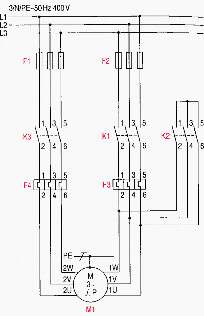
Figures 1a, 1b and 1c illustrate the circuit diagrams for a pole-changing three-phase induction motor with a single winding (Dahlander connection) for two speeds and one direction of rotation.
Figure 1a – Main circuit diagram for a pole-changing three-phase induction motor with one winding (Dahlander connection) for two speeds and one direction of rotation

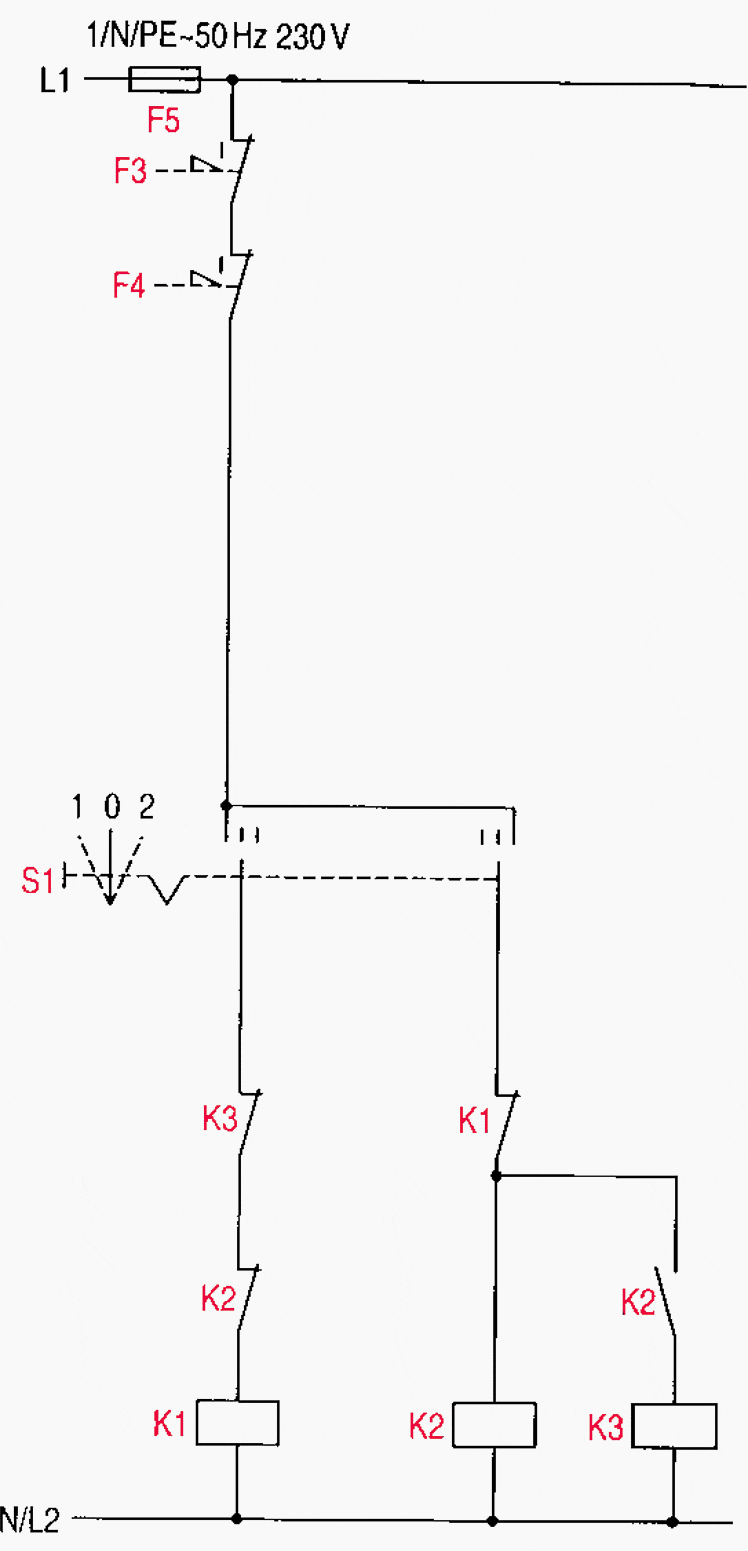
1.1 Pushbutton control momentary contact (Fig. 1b)
Switching on: Contactor K1 is energized by the actuation of momentary-contact switch S1. Sealing-in contact K1 closes and the motor starts up at low speed.
Change-over: Contactor K1 is de-energized by the actuation of momentary-contact switch S2 and the opening of its NC contact. Contactor K2 is energized by the closing of the NO contact of S2. This energizing command on K2 only becomes effective once the NC contact of K1 has closed. Sealing-in contact K2 closes.
The line contactor K3 is energized via the NO contact of K2. The motor runs at high speed. The change-over to a lower speed is effected in the reverse order.
Switching off: Contactors K 1 or K2 and K3 are de-energized by the actuation of momentary-contact switch S0. The motor is switched off.
Figure 1b – Auxiliary circuit for momentary-contact control


Required auxiliary contacts:
- Contactor K1 with 1NO+ 1NC,
- Contactor K2 with 2N0+ 1NC,
- Contactor K3 with 1NC,
- Momentary-contact switch S0 with 1NC,
- Momentary-contact switches S1 and S2 each with 1NO+1NC, and
- Overload relays F3 and F4 each with 1NC
1.2 Switch control/maintained contact (Fig. 1c)
Contactors K1 or K2 and K3 are energized, de-energized or changed over by the actuation of maintained-contact switch S1 as indicated by the switch position indicator.
Note on the main circuit: Fuses F1 and F2 have to be selected according to the motor rated currents at both speeds. A common fuse protection of motor contactors K1 and K3 is permissible if the motor rated currents vary only slightly from each other and if the overload relays F3 and F4 can be used with the same setting ranges.
Figure 1c – Auxiliary circuit for maintained-contact control

Required auxiliary contacts:
- Contactors K1, K3 each with 1NC,
- Contactor K2 with 1NO+1NC,
- Maintained-contact switch S1 with three switch positions, and
- Overload relays F3 and F4 each with 1NC.
Go back to the Contents Table ↑
2. One winding (Dahlander connection), two speeds, two directions of rotation
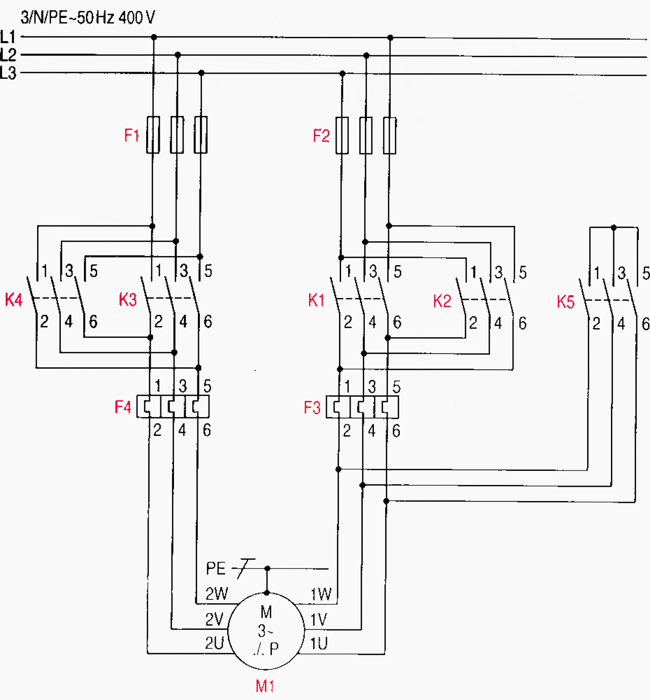
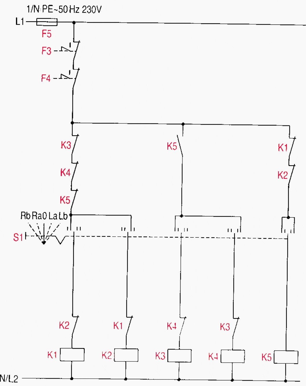
Figures 2a , 2b and 2c illustrate the circuit diagrams for a pole-changing three-phase induction motor with one winding (Dahlander connection), two speeds, and two directions of rotation.
Figure 2a – Main circuit diagram for a pole-changing three-phase induction motor with one winding (Dahlander connection) for two speeds and two directions of rotation

2.1 Pushbutton control/momentary contact (Fig. 2b )
Switching on the motor e.g., for clockwise rotation: Contactor K1 is energized by the actuation of momentary-contact switch S1. The sealing-in contact K1 closes. The motor is switched on at low speed.
Change-over to high speed: Contactor K1 is de-energized by the actuation of momentary-contact switch S3 and the opening of its NC contact. Star contactor K5 and contactor K3 are energized by the closing of the NO contact of S3.
Change-over to low speed: The change-over to low speed is effected in the reverse order.
Change-over to anti-clockwise rotation (high speed): Contactor K3 is de-energized by the actuation of momentary-contact switch S4 and the opening of its NC contact. Contactor K4 is energized by the closing of NO contact S4.
Change-over to anti-clockwise rotation (low speed): The change-over at low speed is accomplished in the same way as with high speed, but by the actuation of momentary-contact switch S2.
Switching off: By the actuation of momentary-contact switch S0 all the contactors in the circuit are de-energized and thus the motor is switched off.
Figure 2b – Auxiliary circuit for momentary-contact control


Required auxiliary contacts:
- Contactors K1, K2. K3, K4 each with 1NO+2NC,
- Contactor K5 with 2NO+1NC,
- Momentary-contact switch S0 with 1NC,
- Momentary-contact switches S1, S2 each with 1NO+2NC,
- Momentary-contact switches S3, S4 each with 2NO+2NC, and
- Overload relays F3 and F4 each with 1NC
2.2 Switch control/maintained contact (Fig. 2c)
Contactor K1 or K2 is energized for low speed in clockwise or anti-clockwise rotation respectively, depending on which switch position of the maintained-contact switch S1 has been selected. This energizing command only becomes effective if the NC contact of K1, alternatively K2, is closed.
Figure 2c – Auxiliary circuit for maintained-contact control

Required auxiliary contacts:
- Contactors K1, K2, K3, K4 each with 2NC,
- Contactor K5 with 1NO+1NC,
- Maintained-contact switch S1 with 5 switch positions, and
- Overload relays F3 and F4 each with 1NC.

