
Estimated Study Time: 8 minutes
To protect persons and LV instalations
The prime function of an earth electrode is the protection of persons. That’s it. It is a fact that we live on Earth! And it is vital to earth exposed metal parts of electrical equipment to avoid electrocution by indirect contact should an insulation fault occur. This measure has been stipulated in the standards a long time ago, since 1923 (IEC 364; NF C 15-100).
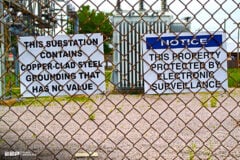
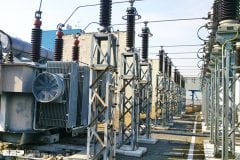
 What is the prime function of an earth electrode in power system (photo credit: stationproject.wordpress.com)
The fault current varies in strength according to the earthing system used, and measures are taken to ensure that contact voltage does not exceed conventional safety voltage for a stipulated time: UL (50 V in AC). The exposed metal parts of electrical equipment are connected to the PE protective conductors in turn connected to the earth, thus forming the earthing arrangement.
The second function of an earth electrode is to minimize common mode disturbances external to the LV installation. An example is 50/60 Hz overvoltage in the event of:
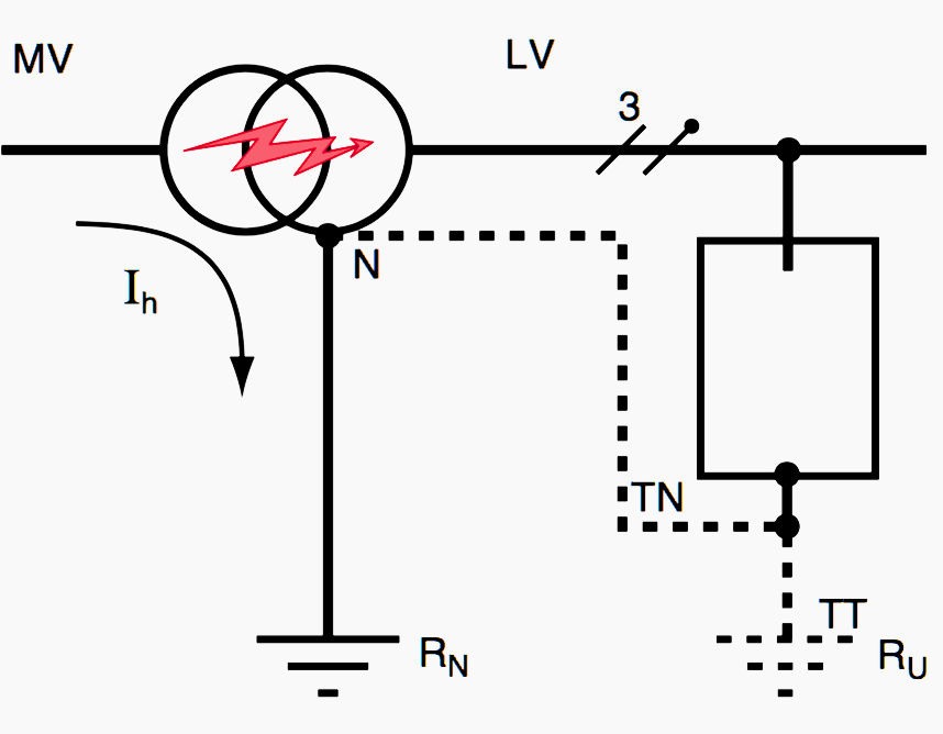
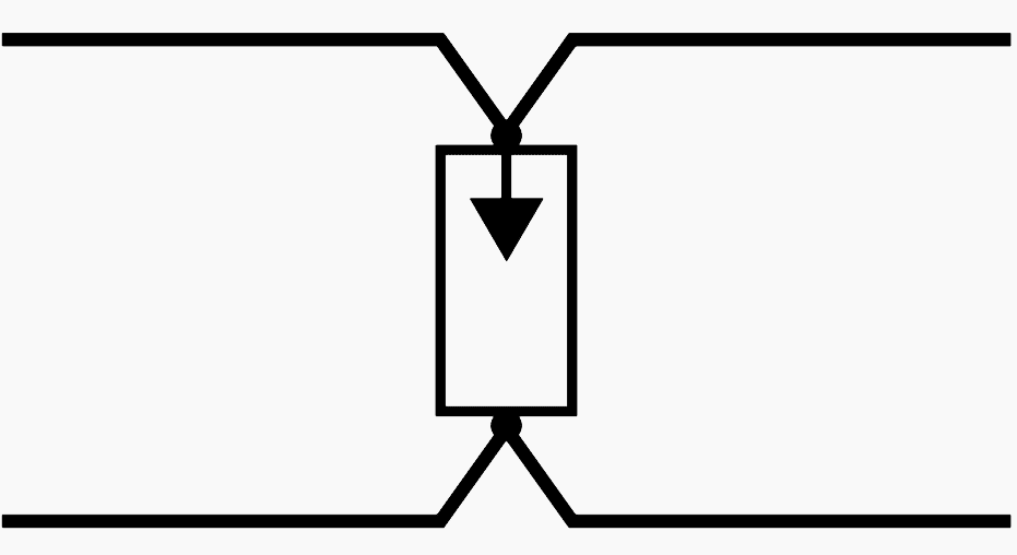
- MV/LV transformer breakdown (see figure 1) or
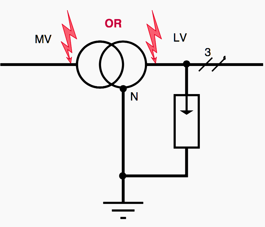
- Overvoltage due to lightning (see figure 2).
MV/LV breakdown – The power system potential rises with respect to the earth: U = RN × Ih resulting in risk for the equipment in TT system or for persons in TN system if the building is not completely equipotentially bound.
Lightning surge – The power system is subjected to pulsating overvoltage on all live conductors, resulting in a high EMC risk. Requires use of lightning arresters whatever the earthing system used.
With reference to the above, NF C 13-100 has laid down limit earth electrode values in France. Lightning, MV/LV faults and safety of persons call for use of low impedance earth electrodes (IhMV can reach 1000 A and the insulating voltage of sensitive devices is 1500 V !). This problem particularly needs to be managed in TT earthing systems.
For a spike: Rp = ρ / L
For the foundation ditch loop: RFF = 2ρ / L
where L is the length of the spike or the perimeter of the loop.
The earth electrode must be a solid copper or stainless steel conductor so as to limit oxidation. Ground resistivity (ρ) is an important parameter, varying considerably with ground humidity and nature from 1 to 5000 Ω/m. It is vital to place the ‘right’ earth at the bottom of the foundation ditch around the loop conductor (see figure 3).
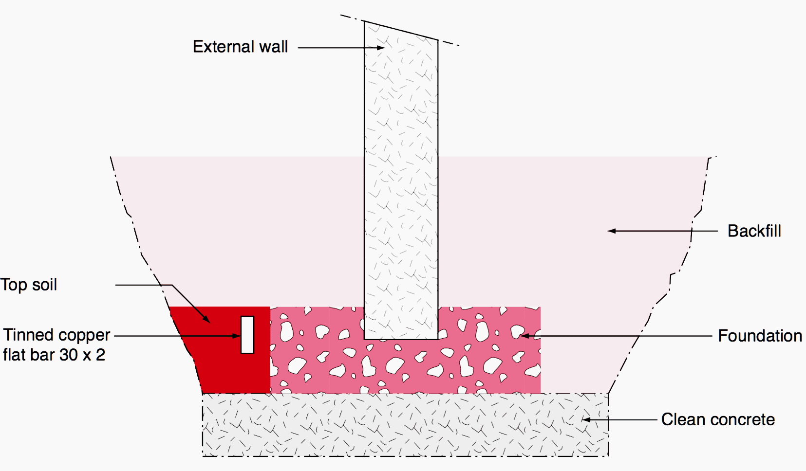
The impedance of an earth electrode varies only slightly between 50 Hz and 500 kHz. If the building is equipped with lightning rods, the rod downcomers must be connected to earth electrodes in triangular crossbracing.
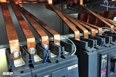
All conductors which might be required to convey lightning currents must be flat conductors in order to reduce the self-induction factor and skin effect and consequently the drop in linear voltage (see figure 3).
Calculation
Continuous resistance of a conductor
Continuous resistance of a conductor is RC = ρ l / s , i.e. RC = 1.7 mΩ for a 10 m long cylindrical copper conductor with a 100 mm2 cross-section. As frequency increases, the skin effect strengthens this resistance.
For copper:
- δ (50 Hz) = 9.3 mm,
- δ (1 MHz) = 65.8 μm,
- δ (10 MHz) = 21 μm.
As a result the real cross-section of the conductor decreases. The ratio between RHF and RC is given for a cylindrical conductor with a radius r by:
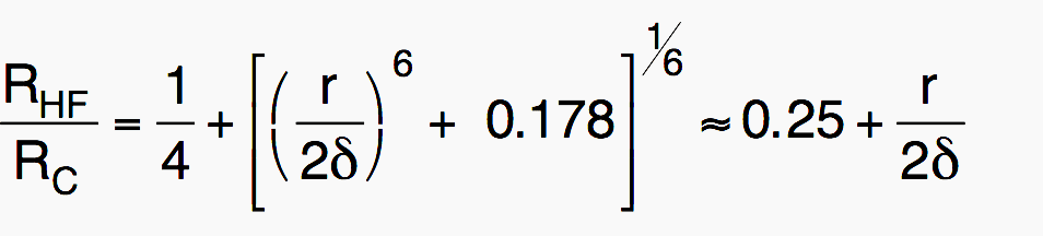
This formula only applies if the radius r of the conductor is greater than the skin depth δ. Our copper conductor is such that:
- at 50 Hz: RHF = RC = 1.7 mΩ,
- at 1 MHz: RHF = 43.1 × RC = 73 mΩ,
- at 10 MHz: RHF = 135 × RC = 230 mΩ.
The self-inductance L (μH) of a conductor
The self-inductance L (μH) of a conductor of a length l is:
- For a cylindrical conductor:

- For a conductor with rectangular cross-section:
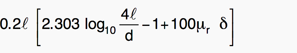
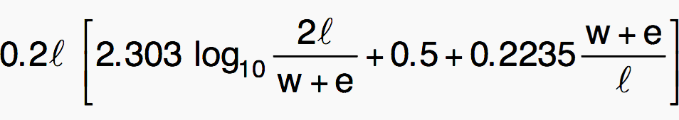
Where l, d(diameter), δ, w (width), e (thickness) are expressed in meters.
Impedance of conductors depending on their geometry and frequency
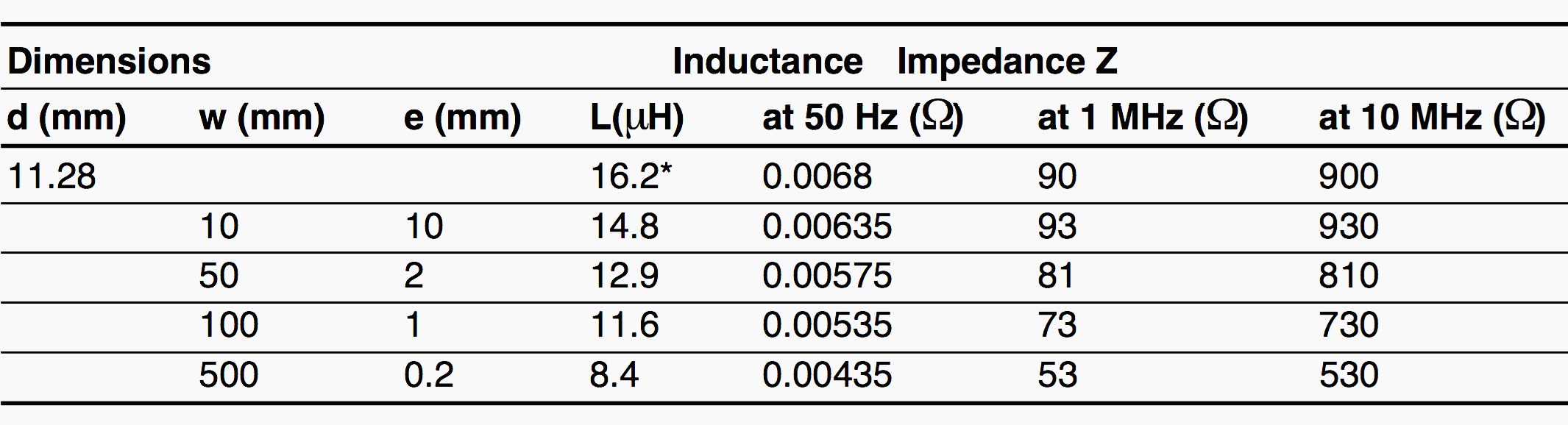
Self-inductance and impedance of a 10 m long copper conductor with a 100 mm2 cross-section depending on its geometry.
(*) in the table the self-inductance of the cylindrical conductor is given at 50 Hz. In HF the term 100 μr, δ becomes negligible, and L ≈ 14.35 μH becomes, like the rectangular cross-section conductor, independant of frequency. Finally note that in HF the impedance Z = 2π×f×L becomes preponderant compared with the resistance RHF.
Let us take the example of an LV lightning arrester designed to limit common mode voltage to 1.5 kV. If it is connected between the protected phase and the earth strip by a 1 m long conductor with circular cross-section, a 5 kA current and a 8 μs rising edge, it will develop the following voltage:
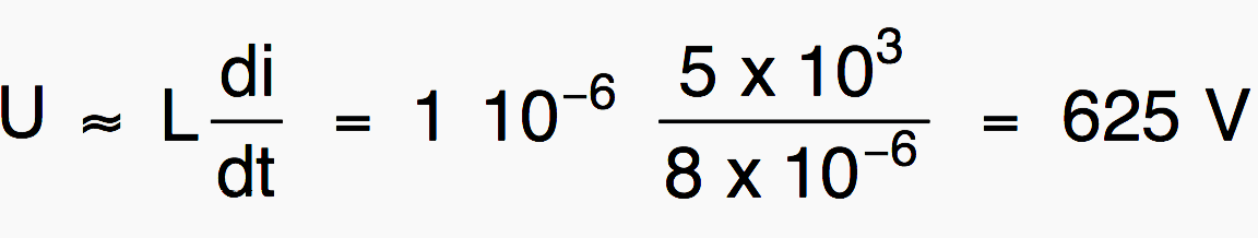
Hence a total overvoltage of 2.1 kV which is dangerous as many devices have an impulse voltage withstand of 1.5 kV. The solution is to connect the application directly to the terminals of the lightning arrester (see figure 4).
[TP]
Lightning protection and earthing system design for Buildings
Reference // Cohabitation of high and low currents by R. Calvas and J. Delaballe
Related electrical guides & articles


Edvard Csanyi
Hi, I'm an electrical engineer, programmer and founder of EEP - Electrical Engineering Portal. I worked twelve years at Schneider Electric in the position of technical support for low- and medium-voltage projects and the design of busbar trunking systems.I'm highly specialized in the design of LV/MV switchgear and low-voltage, high-power busbar trunking (<6300A) in substations, commercial buildings and industry facilities. I'm also a professional in AutoCAD programming.
Profile: Edvard Csanyi

It must also be considered the role of earth electrodes in touch and step potential.