
Estimated Study Time: 26 minutes
Generator Overhauling
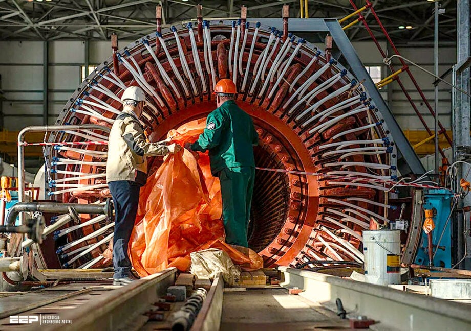
This discussion will focus on the on-site overhauling of a gas-powered generator, detailing the essential procedures for its enhancement. It is a common practice for utilities to test electrical assets periodically after a certain interval of time mainly as part of the activities when a complete turnaround of the plant takes place to replace, upgrade or identify any impending abnormalities within the plant equipment.
 Maintenance Practices to be Followed for On-Site Generator Overhauling
In case of electrical testing, previous tests serve as a blueprint, considering which the current testing results are assessed and a decision is made as to what further action should be taken.
The decision could end up either as “no further action seems to be necessary at this point after satisfactory results”, or “It is better to overhaul the machine and go for its refurbishment after degrading results”.
Because we may obtain results without any signs of trouble as yet but a visual inspection of the actual physical state of the machine windings is critical in deciding that now is the time that it should be refurbished otherwise the accumulation of dust/fumes or other foreign particles could impact the winding drastically until the next cycle approaches.
- Overhauling of a Gas-Driven Generator On-Site
- Electrical Testing After Shutting Down the Unit
- Removal of Rotor
- Bearing Clearances
- Bearing Removal
- Inspection of All Parts
- Testing of Wedges of Stator Winding
- Generator Stator Refurbishment
- A Peek into the Arrangement of Coils Inside Stator
- Mitigation of Partial Discharges
- Main Rotor and Exciter Generator
- Actions Post Re-assembly
- Conclusion
- BONUS (PDF) 🔗 Download Handbook of Electric Machines and Drives
1. Overhauling of a Gas-Driven Generator On-Site
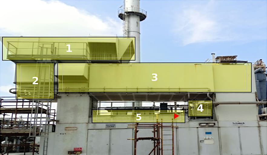
Here we’ll talk about the overhauling of a gas-driven generator on-site (pictured below) including the necessary steps required to better refurbish the unit. The actions required for the removal of the generator from its canopy/gen-turbine unit can be listed as,
- Removal of ventilation air duct
- Lube oil radiators
- Combustion air duct
- Electrostatic filters
- Generator Roof
Figure 1 – On-site gas-driven generator
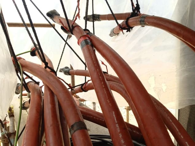
As far as the removal of generator-turbine coupling is concerned, the inadequate space surrounding it could require the removal of starting motor and shaft pump (connected to turbine) to better work around it. At the same time, the electrical team can work on removing the generator power and control cables from its junction box.
It is better to mark the control cables and their termination points on the connecting strips in the junction box so as not to err while reconnecting.
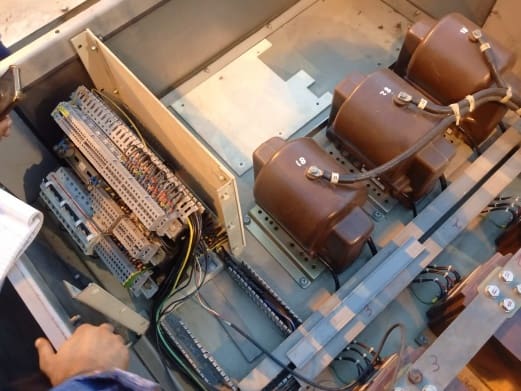
The control cables are used mainly for:
- Winding temperature sensing RTDs
- Bearing temperature sensing RTDs
- Field ground (64F relay) sensing circuit
- Auxiliary winding (in case of AREP excitation)
- AVR output to exciter generator field (in case of brushless excitation)
- Current and Potential transformers
Figure 2a – Picture showing generator power cables
In order to avoid any hassle after start-up, it is better to note down the readings from all the sensors before shutting down the unit or after shutting down the unit while the control supply is still on so that any anomalous reading found after start-up could be better assessed.
For instance, if a bearing temperature sensor is known to be faulty and shows up an abnormal reading even before the shutdown, then any reading similar to that post-start-up could intrigue the control room operator who either doesn’t have any knowledge of such a sensor or assumes the faulty sensor has been replaced during shutdown when it actually hasn’t been and doesn’t confirm it with the maintenance personnel who also seem to have no idea about it.
So, just by referring to the readings straightaway prior to the shutdown, any hasty actions can be prevented.
Figure 2b – Picture showing generator control cables
2. Electrical Testing After Shutting Down the Unit
Once the generator is shut down, do perform the electrical testing of entire set including the exciter generator as well in case of brushless excitation and note down the results so that the values could be compared with the ones obtained after refurbishment.
Following tests can be performed:
- PI, DAR and IR of stator winding
- IR test of rotor winding
- PD test of stator winding
- Winding resistance test of stator & rotor winding
- IR test of exciter generator field and armature winding
- Winding resistance test of exciter generator field and armature winding
- IR test of AREP windings
- Winding resistance test of AREP windings
Here generator power cables disconnected from generator can also be tested for insulation health.
3. Removal of Rotor
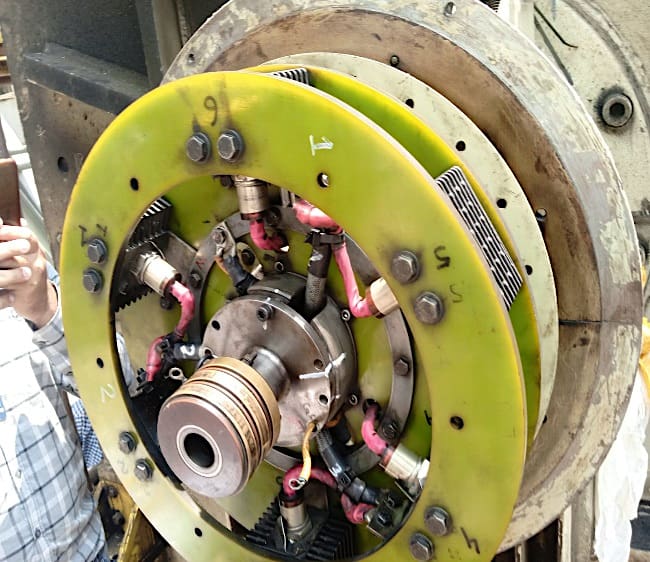
Once the generator has been freed from its canopy and moved to a suitable space, one conducive to the movement of overhead cranes, the next major step is the extraction of rotor from the generator. In the lead-up to the rotor removal, diode assembly mounted on NDE side, is removed first.
Figure 3 – Diode assembly
4. Bearing Clearances
The next step is the removal of bearings from the generator. But before doing so, it is necessary to note down the bearing clearances on both sides. One can find out the bearing clearance by either of the two methods,
Method #1
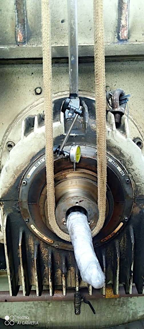
In the first approach, a dial gauge is fixed onto machine shaft and the shaft is lifted upwards with an overhead crane. Then the shaft is released and the reading on the gauge is noted down.
Figure 4 – A dial gauge is fixed onto machine shaft and the shaft is lifted upwards with an overhead crane
Method #2
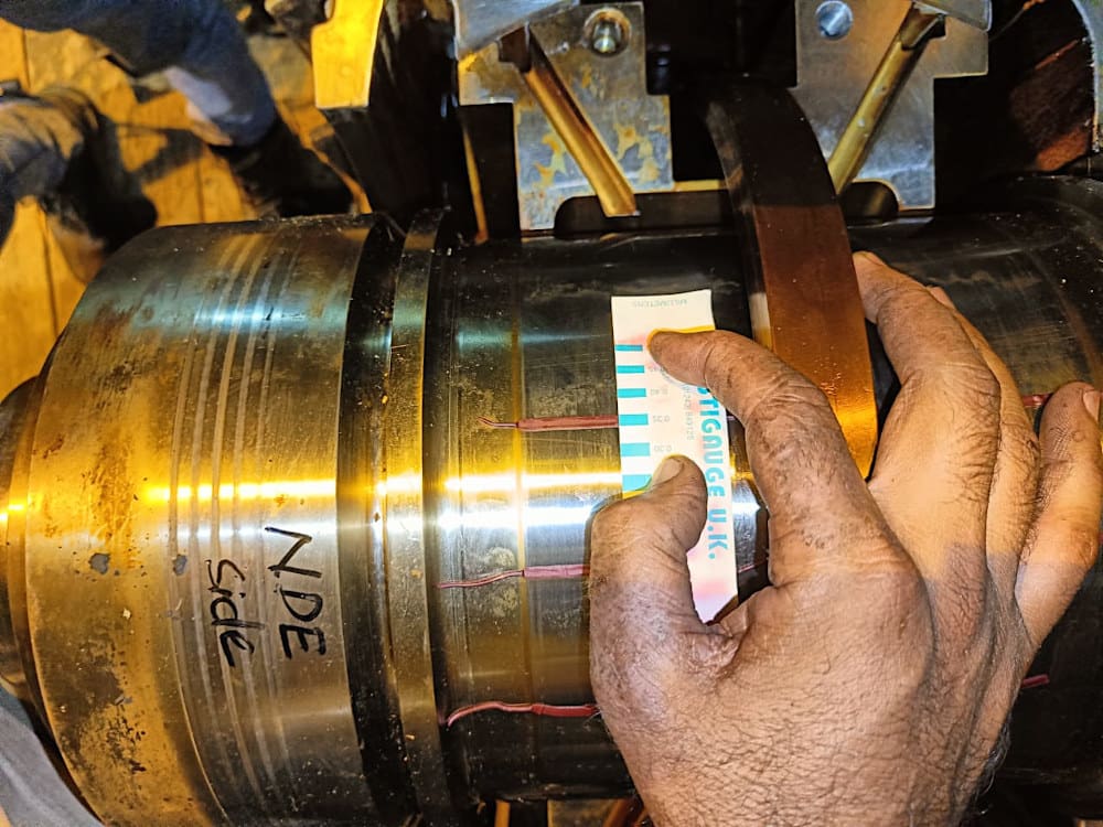
Another way is to use a plastic gauge, a thin wire-like strip, which is placed onto the shaft and then the upper half of bearing is tightened onto it. Width of the deformed plastic gauge measured on a scale indicates the bearing clearance.
Figure 5 – Using a plastic gauge, a thin wire-like strip
5. Bearing Removal
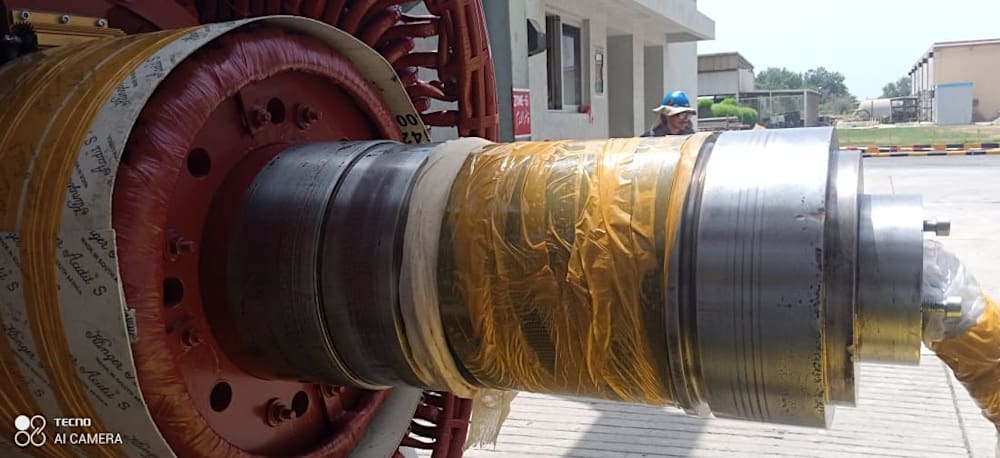
For removal of the bearing, the shaft of the machine is extended with a pipe on whichever side offers the ample space, while a support is provided underneath the pipe in order to support the shaft during and after bearing removal and help with the rotor removal subsequently. If the unit is a brushless excitation system, then it must be having a small exciter generator whose armature (rotor in this case) is mounted on the same shaft and field winding is bolted to the end cover.
Usually, there is very little airgap between field and armature of the exciter, even less than 2 mm.
Figure 6 – Extension Pipe Connected on DE Side
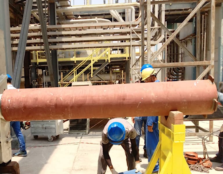
Figure 7 – Generator Bearing Removal
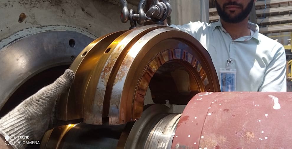
After the removal of bearing, the surface of the shaft where bearing is installed should be covered properly as shown in the attached picture,
Figure 8 – Properly Covered Bearing Area
It is better to loosen the exciter field from the end cover so that when bearing is removed from either side, the field now simply rests on the exciter rotor (with an airgap twice the normal at the bottom between them) so that any probable exaggerated movement of shaft during bearing removal doesn’t culminate in exciter rotor pressing on the exciter field.
Similarly, a machine seal bolted to the end cover should be loosened first as well.
Related electrical guides & articles


Umer Nasir
I am an electrical engineer specializing in electrical power, with experience in the operation and maintenance of Low- and Medium-voltage electric machinery and switchgear, life assessment testing, troubleshooting, and root cause analysis of various failures associated with electrical machinery.Profile: Umer Nasir
