The need for maintenance
Like any other major component of the high voltage electrical network, a switchgear also needs maintenance schedules for trouble-free operation during its life cycle. No one should work on the system itself or on any plant controlled by it, without obtaining authorisation and work permit from the responsible person.
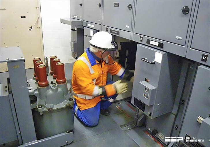
Once such work has started, then it should not be possible for someone to re-connect the supply accidentally to the associated system or plant. Reconnection of supply should be done only after the work permit has been taken back by the concerned authority.
In order to ensure that this safety precaution is implemented, inter-lock and padlocking features are provided on the switching devices.
- Maintenance Requirements
- Inspection Schedule
- Preparation Before Maintenance
- Maintenance Procedure
- Switchgear Spares
- Lubrication of Operating Mechanisms
- Troubleshooting Guide For Older Switchgears
1. Maintenance Requirements
Maintenance covers a wide range of activities, all of which are required to keep the switchgear in ready condition at all times to enable it perform its functions satisfactorily. The parts subjected to normal wear and aging need to be serviced for ensuring full reliability of the operations.
These parts may be mechanical components or electrical components.
The interval at which the maintenance should be carried out depends upon the following factors:
- The number of short-circuit interruptions
- The switching frequency
- The actual service time
The actual conditions of use in terms of the frequency of operations, environment and severity of switching duty vary so much that it is impossible for the manufacturer to give detailed guidelines to the user concerning the frequency of maintenance.
A distinction needs to be made between the basic switching device with its moving parts, and the rest of the equipment which performs the supporting role of connection.
The latter components are likely to need periodic inspection and servicing only, to ensure that the equipment is free from dirt, dampness and deterioration, such as corrosion of metal work and contamination of insulation.
The maintenance of the basic switching unit should be the first priority! For vacuum interrupters, however, no such maintenance is needed.
Applicable standards draw attention to the importance of the methods for determining when various maintenance procedures need to be carried out.
As an example, with vacuum circuit breakers the most likely criterion that needs to be monitored occasionally is contact wear, and the timing of the opening operation.
The O&M manual of the manufacturer normally describes how to perform these operations and the acceptable levels of performance before putting the switchgear back into service. It also gives special instructions for the design of switchgear from maintenance point of view, apart from general switchgear practices.
For example, the proper method to release any stored energy in the closing mechanism before beginning an examination is spelt out.
2. Inspection Schedule
The following guidelines must be included while formulating inspection schedules for switchgear:
Guideline #1
Once a year, a general visual inspection should be carried out and insulators wiped clean. More frequent checks are necessary if the breakers are exposed to a dust-laden atmosphere.
Guideline #2
The operating mechanism should be lubricated after two years or on completion of 2,000 make-break operation at lubrication points for a typical mechanism. After a specified number of operations, the mechanism should be overhauled.
Guideline #3
Constructions of the interruption unit are different for oil, SF6 or vacuum switchgear. Under normal service conditions, vacuum interrupters need no maintenance but in the case of other arc-interrupting media, special care needs to be taken as per the manufacturer’s instructions.
Guideliene #4
Vacuum interrupters must be replaced after the stipulated number of mechanical operations or when the contact erosion has reached its limit, whichever is earlier.
In the case of fully sealed vacuum circuit breakers, manufacturers do not normally recommend examination or overhaul of the pole unit during the economic life of the installation. Moreover, the latest trend is to use gas insulated switchgear (GIS), which is sealed for life. In such designs, carrying out of any maintenance by the staff of the user is not recommended.
In the unlikely event of GIS needing an overhaul, this task should be entrusted to the manufacturer.
Maintenance MUST be carried out by trained staff and guidelines provided in the O&M manual should be followed. Earthing before maintenance is very important.
3. Preparation Before Maintenance
Safety features need to be planned before switchgear units are ordered. The requirement of locking off parts of the system (for carrying out maintenance work on the associated plant) should be finalised. Proper interlocking arrangements should be provided for this purpose.
All metal-enclosed switchgears are designed so that all live conductors are placed behind either metal enclosures or locked/bolted doors.
The use of switchgear to gain access to the system for earthing conductors, for testing cables and other equipment, along with maintaining the switchgear itself is covered below.
The general safety rules mentioned above must also be followed in maintenance of the switchgear. The person responsible for authorising the action must be identified so that all those concerned know the co-ordinator for each procedure.
For example, when the system needs to be earthed at a point, all possible supply routes to that point should be locked off. The earthing should not open inadvertently till work on the earthed equipment is being carried out.
4. Maintenance Procedure
There are many standards on the subject pertaining to different voltage levels of switchgear, which normally defines four separate aspects of maintenance, with each new stage based on the preceding one,
- Inspection,
- Servicing,
- Examination and
- Overhaul.
These are dealt with in detail below:
4.1 Inspection
This is a maintenance action, which calls for a careful scrutiny of a switchgear component. The inspection is carried out without dismantling the component from its assembly.
4.2 Servicing
Servicing implies work that is carried out for ensuring that the equipment is kept in an acceptable condition. It does not involve any dismantling, and is typically limited to cleaning, lubrication and adjustments as specified in the operation and maintenance (O&M) instructions of the switchgear.
4.3 Examination
This is an inspection carried out with partial dismantling, as required, supplemented by means such as measurement and non-destructive tests in order to arrive at a reliable conclusion about the condition of a particular switchgear component.
4.4 Overhaul
Work done with the objective of repairing or replacing parts, which are found to be below standard by examination, so as to restore a particular component or the entire equipment to an acceptable condition, is referred to as overhauling.
A study of above definitions indicates the possibility of an interference in the form of maintenance. Inspection may lead to the conclusion that servicing is needed. The maintenance engineer may sense a problem and call for a detailed examination.
After examination, an overhaul may be needed.
However, proper spares must be available at site for safe operation of switchgear units to their full rating.
5. Switchgear Spares
Switchgear spares are needed to change the maintainable parts after their useful life is over. Sometimes replacement is required if a fault develops in the parts. This is to ensure a reduction in the downtime and enhancement of reliability. A switchgear operating engineer always likes to keep all necessary spares in his stock but a balance needs to be maintained between inventory cost and chances of failure of the component.
The spares needed for a switchgear site are covered in the following broad categories:
5.1 Commissioning spares
These include items that are consumed during pre-commissioning tests. Typically, these spares include indicating lamps and fuses.
5.2 Recommended spares (For 2/4/5 years of normal operation)
These include items which are recommended by the manufacturer to be kept at site. The quantities of these items vary with the time period.
5.3 Mandatory spares (For 2/4/5 years of normal operation)
These include items needed by the user irrespective of any recommendation of the manufacturer for the specified time of operation.
Table 1 gives a typical list of the recommended spares for vacuum switchgear. This list is, however, not exhaustive. In all cases, the recommendations of the switchgear manufacturer should be followed.
Table 1 – List of Recommended Spare Parts for Vacumm Switchgears
No. | Item Description |
1 | Spare breaker (VCB truck) a) 2500 A b) 2000 A c) 1600 A |
2 | Spring charging motor |
3 | Closing coil |
4 | Shunt trip coil |
5 | Bus support insulator |
6 | Set of control fuses (30 fuses) |
7 | Indicating lamps with fittings |
8 | Spring charging limit switch |
9 | Breaker control switch |
10 | Auxiliary switch |
11 | Push button |
12 | Anti-pumping relay |
13 | Meter of each type: a) Ammeter b) Voltmeter |
14 | Vacuum interrupter |
15 | CT and VT of each ratio (one each) |
16 | Set of protection relays: a) Set of relay (one of each type) |
17 | Limit switch (1NO+1NC) |
18 | Panel operating switches a)Switchgear selector switch b) Auto/Individual/Manual selector switch c) Trip selector switch d) Synchronisation selector switch e) On/Off switch for ac supply f) On/Off switch for dc supply |
19 | Set of fixed isolating contacts (1 set comprising 6 numbers) a) 2500 A b) 2000 A c)1600 A |
20 | Set of gaskets |
21 | Panel door keys |
6. Lubrication of Operating Mechanisms
Timely lubrication with recommended lubricating oil ensures trouble-free operation of the components of a switchgear mechanism. The cover must be removed to lubricate the mechanism parts. All appropriate points need to be lubricated, starting at the top left and working through the mechanism systematically.
Table 2 gives a list of the lubricating points for a typical vacuum circuit breaker.
Table 2 – Lubricating points
No. | Lubricating Part / Point |
1 | Bearings, sliding surfaces and levers of operating mechanism |
2 | Connecting joints and rollers of operating mechanisms and bearings of auxiliary switch |
3 | Contact faces for connections and terminal faces of vacuum interrupter |
7. Troubleshooting Guide
The following paragraphs give troubleshooting guide for a an older vacuum circuit breakers. Such guidelines should be provided by the manufacturer of the switchgear for ready reference in case of any trouble with the operation of the switchgear.
The various components mentioned in the tables can be seen in the relevant photos.
7.1 Outdoor Porcelain-clad Vacuum Circuit Breaker
Trouble #1 – Pole Bursting


No. | Reasons | Remedial Action |
1 | Failure of porcelain insulator due to hair cracks developed during transportation | Replace porcelain insulator |
2 | Failure of operating rod due to ingress of moisture | Replace operating rod and gasket. Ensure positive pressure inside the pole unit assembly. |
3 | Failure of vacuum interrupter due to vacuum loss or ingress of moisture | Replace vacuum interrupter. |
4 | Failure of outdoor CT which damages the porcelain insulator of breaker | Investigate CT failure and replace it. |
Trouble #2 – Flashover in Top/Bottom Porcelain
No. | Reasons | Remedial Action |
1 | Contamination of insulator | Clean porcelain insulator. Frequent cleaning may be required depending upon the local environment condition. Check IR value, if found to be less than 10,000 mega-ohm, then replace insulator. |
2 | Dropping of metallic items such as wires by human or birds, climbing of animals and creeping of reptiles | Care should be taken to:
|
Trouble #3 – Excessive Heating of Terminal Connectors
No. | Reasons | Remedial Action |
1 | Loose connection | Tighten terminal connectors properly |
2 | Load more than the specified rating | Reduce load suitably |
7.2 Indoor Metal-clad Vacuum Switchgear
Trouble #1 – Flashover in insulating parts
No. | Reasons | Remedial Action |
1 | Support insulator failure | Clean the insulator with clean cotton cloth, take IR value using 5 kV megger between busbar and panel. If value obtained is less than 10,000 mega-ohms, replace the insulator.![]() ![]() ![]() ![]() |
2 | Inter-panel insulating barrier failure | Clean the barrier with clean cloth, take IR value using 5 kV, megger between busbar and panel earth. If value obtained is less than 10,000 mega-ohms, replace the barrier.![]() ![]() |
3 | Insulating rod failure | Take IR value using kV, megger between inserts of operating rod. If value obtained is less than 10,000 mega-ohms, replace the operating rod. |
2 | Insulating shutter surface tracking | Replace the shutter.![]() ![]() |
2 | Insulation failure due to reptiles | Replace the damaged material. Care should be taken to ensure that doors and covers of the breaker panels are fully closed. The openings provided for earth bus, LT and HT cables should be sealed properly to avoid entry of reptiles. |
Trouble #2 – Vacuum Interrupter Failure
No. | Reasons | Remedial Action |
1 | Vacuum loss | Vacuum loss can be checked by applying HV for one minute across terminals of vacuum interrupter after withdrawing breaker truck outside the panel. If it fails to withstand and flashover occurs, then vacuum interrupter should be replaced by new vacuum interrupter.![]() ![]() |
Trouble #3 – CT/VT failure
No. | Reasons | Remedial Action |
1 | External flashover due to insulation fialure | If cracks or burning marks are ob-served, then replace current transformer and/or voltage transformer. |
2 | CT saturation | This should be checked by giving secondary current through auto-transformer and measure primary current. If meter reading does not increase with the increase of current in secondary, it indicates CT saturation. Then replace CT. |
Trouble #4 – Excessive Above
No. | Reasons | Remedial Action |
1 | Loose connections Heating of Joints | Tighten all the joints properly 40-45 Nm torque. |
7.3 Spring-Charged Mechanism


Trouble #1 – Breaker not closing
No. | Reasons | Remedial Action |
1 | Motor not charging spring due to supply voltage less than 85% | Ensure supply voltage above 85% of the rated voltage.![]() ![]() |
1 | Motor not charging spring due to improper wiring | Check motor circuit wiring as per schematic drawing. If loose connections are found, tighten them. |
1 | Motor not charging spring due to jamming of gear box | Replace gear-box.![]() ![]() |
1 | Motor not charging spring due to motor shaft being broken or motor key being broken | Replace motor.![]() ![]() |
1 | Closing coil burnt due to plunger stuck in closing coil | Replace closing coil.![]() ![]() |
1 | Closing coil not developing sufficient force | Check the resistance of coil at respective voltage, if not adequate, then replace the coil. |
1 | Mechanism linkage setting disturbed | Setting should be done as explained in the operation and maintenance manual of the switchgear.![]() ![]() |
1 | Auxiliary switch continuity missing due to contamination of contacts | Open the auxiliary switch packets and clean the contacts.![]() ![]() |
Problem in electrical circuit | Check the circuitry and replace the faulty components.![]() ![]() |
Trouble #1 – Breaker not opening
No. | Reasons | Remedial Action |
1 | Tripping coil not developing sufficient force | Check the resistance of coil at respective voltage, if not adequate, then replace the coil.![]() ![]() |
1 | Tripping coil burnt due to plunger stuck in tripping coil. | Replace tripping coil. |
1 | Problem in tripping circuit. | Check the circuitry and replace the faulty components. |
1 | Mechanism linkage setting disturbed | Setting should be done as explained in the operation and maintenance manual of the switchgear.![]() ![]() |
Source: Switchgears book by BHEL – Bharat Heavy Electricals Limited
Related electrical guides & articles
Premium Membership


I am looking for a service provider to do maintenance on our switchgear. We are a bio-pharma company located in Frederick, Maryland. Please let me know if there are any company you recommend for switchgear maintenance. The must be certified in the area since we are regulated by the FDA and will need to provide the required certification documentation for work done on our equipment
please send me document for Diagnosis and troubleshooting of the high voltage switchboard.thanks
That caption for the very first photo should read 11kV not 66kV. I recognize the substation.
Very important lessons you have given. Thank you
Maintenance & Testing of (HT & LT) motor, generator and transformers.
Please I’m interested in all your engineering works
So amazing note; I’ve not had it this good. Thank you Boss.
It is an important lesson for an Electrical should know. Thank a lot for sharing.
Number 6 Ogidi Street Garki ll Abuja Nigeria.
This is the best thing that happened to me today.
A very Good and Insightful piece, please keep it up and more Grace to you and your team.
Keeping good work all time power volts thank you to you service
Good video.
Very good and educative knowledge is given through EEP. Thanks.
I really love this, I wish to read this everyday an wish to do this practically hence I have N5 In electrical engineering heavy current an ultrasonic wall thickness hence I worked at different power stations as wall thickness technician inspecting boiler an turbine thou is not permanent job so far due to reason that I put my heart in everything I would like to be assert of this company please hence my contact information. 0797033230 am available an unemployed at the moment.
Cordial saludo desde Colombia Suramerica, excelente el aporte que día a día nos entrega por el portal, deseándole éxitos y agradecer por tan valioso aporte técnico.