
Estimated Study Time: 20 minutes
MV/LV Switchboards in general
Depending on the size of the building or factory site and whether the supply is high voltage or low voltage, there may be requirements for both a main high voltage switchboard and one or more low voltage switchboards or just a single low voltage switchboard. The preferred name for the switchboard unit is a “Switchgear and Controlgear Assembly” (SCA).
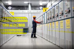
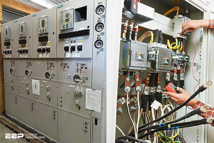 Major components you can spot while looking at opened LV and MV switchboards (on photo: Siemens gas insulated switchgear, 38KV, 1250 on left; LV switchboard and electrician performing testing on right)
The basic aim of the switchboard is to take the electrical power from the main supply source and then to feed or distribute power to the appropriate circuits within the building. The switchboard has to perform this function in such a way that there is proper control of power flow and proper electrical protection against the damaging effects of faults.
This protection is necessary to prevent personnel hazards and also equipment hazards and possible fires. It should be able to operate to isolate a faulty section in the minimum possible time consistent with the fault severity.
In many cases, work is performed on the switchboard components while they are still live.
Components of MV and LV Switchboards
LV and MV are different despite they may look very similar. One thing they do the same is that they distribute electrical energy, but using different voltage levels. MV will always supply LV switchbord, never vice versa.
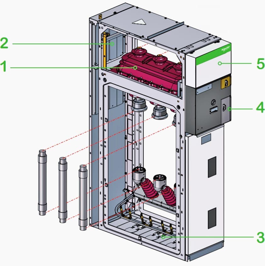
1. The major components of a MV switchboard:
2. The major components of a LV switchboard:
1. MV switchboard
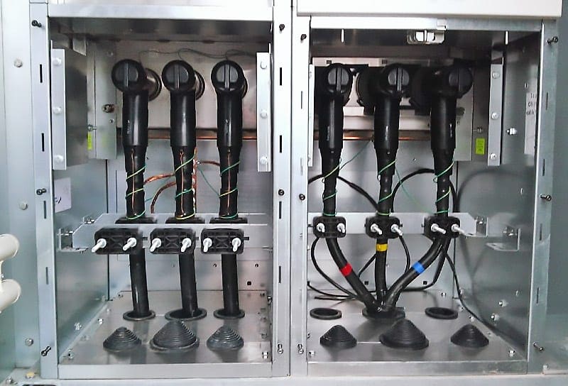
1.1 The Incoming Cables
These may be either high voltage (HV) or medium or low voltage (MV or LV). For high voltage, they will normally be either impregnated paper insulation (unlikely these days), cross linked polyethylene (XLPE) or ethylene propylene rubber (EPR) insulated cable.
The last two types are the preferred types for new installations, with XLPE being the most common.
In some cases busbars can be used instead of cables. This option is far more expensive than cables, but it also offers better reliability. If you ask me, I prefer busbar systems, where applicable of course.
1.2 Outgoing circuit conductors
These may be any of the following types:
- Insulated cables,
- Insulated busbars,
- Busbar trunking systems
- Mineral insulated metal-sheathed (MIMS) cables
- Fire-resistant cables
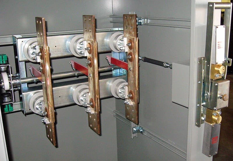
1.3 Knife Switch
Knife-switches are used in MV switchgear to isolate specific equipment or feeders for maintenance or other purposes such as earthing. They operate at no-load conditions by hand, or in remote-controlled installations, they are actuated by motor or compressed air.
Blades of knife-switch, mounted standing or suspended, must be prevented from moving spontaneously under their own weight. The physical size of this type of switches must be taken into consideration when deciding the dimensions of the switchgear.
Usually, the switchgear requires greater depth.
1.4 Load-break switch
Load-break switches are increasingly being used in MV distribution systems. For instance, ring main units use load-break switches in the two incoming feeders that connect the consumer’s substation to the network.
Two mechanisms can be used for load-break switch operation:
- Snap-Action Mechanism: A spring is tensioned that is released shortly before the switching angle is completed. Its force is used to move the contacts. The procedure is employed for both closing and opening.
- Stored-Energy Mechanism: It has one spring for closing and another for opening. During closing operation, the opening spring is tensioned and latched. The stored energy for opening operation is released by means of a magnetic trip or fuse.
Mainly two types of load-break switches are used: knife-contact type with/without fuses and slide-in type with/without fuses.
Where:
- Switchgear: Switch-disconnector and earthing switch in an enclosure filled with SF6 and satisfying “sealed pressure system” requirements.
- Busbars: All in the same horizontal plane, thus enabling later switchboard extensions and connection to existing equipment.
- Connection: Accessible through front, connection to the lower switch-disconnector and earthing switch terminals or the lower fuse-holders. This compartment is also equipped with an earthing switch downstream from the MV fuses for the protection units.
- Operating mechanism: Contains the elements used to operate the switch-disconnector and earthing switch and actuate the corresponding indications (positive break).
- Low voltage: Installation of a terminal block (if motor option installed), LV fuses and compact relay devices. If more space is required, an additional enclosure may be added on top of the cubicle.
1.5 Earthing Switch
Earthing switches are commonly used and installed in switchgear. When isolating any of the feeders (incoming or outgoing) for maintenance, the feeder must be earthed by closing the earthing switch to discharge any static charge carried by the feeder.
The switchgear manufacturer must mechanically interlock the earthing switch with the circuit breaker or load-break switch to avoid severe symmetrical short circuit if they are closed simultaneously.
Related electrical guides & articles


Edvard Csanyi
Hi, I'm an electrical engineer, programmer and founder of EEP - Electrical Engineering Portal. I worked twelve years at Schneider Electric in the position of technical support for low- and medium-voltage projects and the design of busbar trunking systems.I'm highly specialized in the design of LV/MV switchgear and low-voltage, high-power busbar trunking (<6300A) in substations, commercial buildings and industry facilities. I'm also a professional in AutoCAD programming.
Profile: Edvard Csanyi
