
Estimated Study Time: 32 minutes
Seal-in Contacts in Motor Control
In the domain of electrical engineering, seal-in contacts stand as pivotal components in control circuits, ensuring the sustained operation of electrical devices beyond the initial activation. These mechanisms play a critical role in maintaining the energized state of circuit elements, such as contactors, facilitating precise control and enhancing operational efficiency.
 Mastering schematic drawings: Analyzing seal-in contacts in motor control circuits
The integration of seal-in contacts in motor control circuits introduces new avenues for directional control and operational flexibility. Through meticulous design and implementation, engineers can orchestrate seamless changes in motor rotation, optimize performance, and ensure safe operation in dynamic environments.
In this technical article, we will explore the operation of DC motors in both clockwise and anti-clockwise directions revealing the intricate sequence of events orchestrated by seal-in circuits.
From initiating motor rotation to adjusting circuit configurations, each step contributes to efficient and controlled motor operation.
- Seal In Contact
- Why Seal In Circuit is Required
- Exploring the Simple Seal In Circuit:
- Motor Control Circuit Using Seal In Contact:
- Motor Control Circuit for DC Motor Direction Control:
- Clock Wise Operation of DC Motor:
- Anti-Clock Wise Operation of DC Motor
- Motor Stop Circuit
- BONUS! Download Practical Guide to Electric Motor Control (PDF)
1. Seal In Contact
A seal in contact is essentially another normally open contact on a relay. What sets it apart is its specific application within a control circuit. When the relay coil is energized and the normally open contact closes, it forms a feedback loop that maintains the relay in the energized state even after the initiating input signal is removed. This feedback loop effectively “seals in” the relay’s operation.
Hence that normally open contact that keep the coil of auxiliary relay energized is called as seal in contact.
In such systems, the concept of “sealing in” a relay’s operation is crucial for maintaining desired states or sequences of operation even after the initial triggering condition is no longer present.
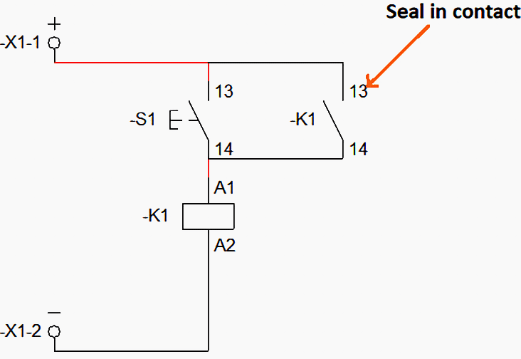
Figure 0a – An example of using the K1 auxiliary contact as Seal In contact
2. Why Seal In Circuit is Required
In the realm of electrical circuits, the integration of seals and contactors serves as a critical aspect in ensuring the efficiency, safety, and reliability of operations. The necessity of incorporating seals and contactors stems from various intricacies and challenges that cannot be adequately addressed by conventional buttons alone.
First and foremost, it is essential to comprehend the limitations associated with traditional buttons. While buttons may seem like straightforward components for circuit control, they are susceptible to a phenomenon known as contact bouncing.
This phenomenon occurs when the button is pressed or released, causing the electrical contacts to oscillate rapidly before settling into a stable closed or open position.
Moreover, conventional buttons are ill-equipped to handle high current loads effectively. As electrical circuits frequently necessitate the transmission of substantial currents, relying solely on buttons can pose significant risks.
Suggested Video – Seal-in or Latching Contct
Enter contactors – robust electromechanical switches specifically designed to accommodate high current capacities. By incorporating contactors into the circuitry, engineers can ensure seamless power transmission without compromising safety or performance.
Additionally, the utilization of contactors facilitates remote control capabilities, enabling operators to manipulate the circuit’s operation from a distance through the application of small control signals, whether alternating current (AC) or direct current (DC).
This inherent characteristic of contactors not only enhances the longevity and efficiency of electrical circuits but also mitigates potential hazards associated with electrical faults.
The advantages offered by contactors in electrical circuits are manifold, rendering them indispensable components in control systems across various industries. From their capability to mitigate contact bouncing issues to their capacity to handle high currents and facilitate remote control functionalities, contactors epitomize efficiency, reliability, and safety in electrical circuitry.
As such, their pervasive utilization underscores their indispensable role in modern control systems.
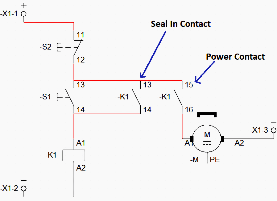
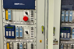
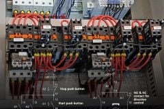
Figure 0b – An example of motor control circuit using contactor for on/off control
In conclusion, the integration of seals and contactors in electrical circuits serves as a fundamental mechanism to address the inherent challenges and limitations posed by conventional buttons.
By leveraging the capabilities of contactors, engineers can ensure optimal circuit performance, mitigate risks associated with contact bouncing, and enhance operational efficiency.
Thus, the significance of seals and contactors in electrical circuits cannot be overstated, as they epitomize the pinnacle of reliability, safety, and functionality in control systems.
3. Exploring the Simple Seal In Circuit
Refer to the Figure 1, showing the push button -S1, with NO contact numbers 13 and 14, a contactor named –K1 with its auxiliary contact NO numbers 13 & 14. Now as soon as the push button –S1 is pressed the contactor K1 is energized and the NO contact of K1 changes its position to close.
Refer to Figure 2 showing the status of the circuit when push button S1 is pressed. But as soon as the contactor operator removes its hand from the push button S1, contactor K1 is de-energized again.
Hence if you connect a motor or any other device through auxiliary contact K1 then the power of that device will also be cut as soon as the S1 switch is reset. Hence the seal in function is not achieved. This limitation underscores the necessity of incorporating seals into the circuitry. A seal serves as a mechanism to maintain the state of the contactor even after the push button is released.
By implementing a seal, the contactor remains energized, ensuring the uninterrupted flow of power to the connected load.
Related electrical guides & articles


Muhammad Kashif
Muhammad Kashif Shamshad is an Electrical Engineer and has more than 17 years of experience in operation & maintenance, erection, testing project management, consultancy, supervision, and commissioning of Power Plant, GIS, and AIS high voltage substations ranging up to 500 kV HVAC & ±660kV HVDC more than ten years experience is with Siemens Saudi Arabia.Profile: Muhammad Kashif
