
Estimated Study Time: 12 minutes
MV switchgear & control issues
There are numerous variations of MV switchgear topology, measurement, and control logic. However, there are also some basic rules related to these aspects which may be frequently seen in practice, with the purpose of increased safety and reliability during operation. Within this article, the real example of MV switchgear with two main busbar sections will be described.
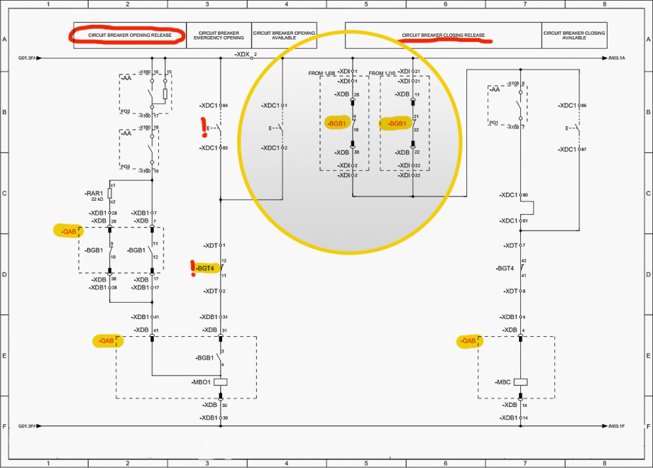 Mastering single line and wiring diagrams: Interlocking between MV cubicles
Most of the attention will be given to concrete practical solutions related to some control issues. This subject will be illustrated by use of adequate single line and wiring diagrams.
Example of MV switchgear
Switchgear which is the subject of this example is installed inside MV/LV substation and serving as the power supply of new factory of construction steel products. There are eight MV/LV power transformers in total, with a rated power of 3.5 MVA each.
Table 1 – Main technical characteristics of MV switchgear
| Construction: | Metal enclosed |
| Installation type: | Indoor |
| Isolation type: | Air insulated (isolation medium inside cubicles) |
| Protection degree: | IP 3X |
| Ambient temperature: | −5 … +40 °C |
| Number of cubicles: | 14 |
| Rated voltage: | 24 kV (*) |
| Operating voltage: | 20 kV (*) |
| Rated lightning withstand voltage: | 125 kV, 1.2/50 µs |
| Rated power frequency withstand voltage: | 50 kV, 1 min. |
| Rated current of main busbars: | 1250 A |
| Rated short time withstand current: | 20 kA × 2 s |
| Rated peak withstand current: | 50 kA |
| Arc test current: | 21 kA × 1 s (**) |
| Internal arc classification (IAC): | AFLR (**) |
| Rated voltage of control and signal circuits: | 110 VDC |
(*) Rated voltage of the switchgear is the upper limit of phase to phase RMS value which switchgear is capable to withstand continuously. Operating voltage is rated (expected) phase to phase value during operation. This value is usually allowed to vary within ±10% limits or less.
(**) IAC parameter defines from which sides MV switchgear is safely accessible during internal fault followed by presence of electric arc. This parameter depends on arc test current value, dimensions of room inside of which MV switchgear is installed, and technical measures taken for dissipation of heat and pressure caused by arc.
Related electrical guides & articles


Miodrag Kokotovic
Graduated from Faculty of Electrical Engineering, within University of Belgrade, in the field of electrical power systems. Expert in electrical part of tender preparation, design, procurement, construction and commissioning of treatment plants and pumping stations, electrical power quality and energy management.Profile: Miodrag Kokotovic
